Humidifying micro-mixing burner

A burner, micro-mixing technology, applied in burners, gas fuel burners, combustion chambers, etc., can solve problems such as inability to meet pollutant emission requirements

Active Publication Date: 2021-05-28
HARBIN INST OF TECH
View PDF21 Cites 4 Cited by
  • Summary
  • Abstract
  • Description
  • Claims
  • Application Information

AI Technical Summary

Problems solved by technology

As the pollutant emission indicators become more and more stringent, the traditional burner can no longer meet the pollutant emission requirements under the above working conditions, so it is necessary to design a new type of humidification micro-mixed burner to solve the above problems

Method used


Image

  • Humidifying micro-mixing burner
  • Humidifying micro-mixing burner
  • Humidifying micro-mixing burner

Examples


Embodiment Construction

[0033] It should be noted that, in the case of no conflict, the embodiments of the present invention and the features in the embodiments can be combined with each other.

[0034] The present invention will be described in detail below with reference to the accompanying drawings and examples.

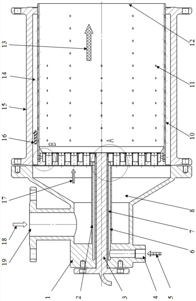
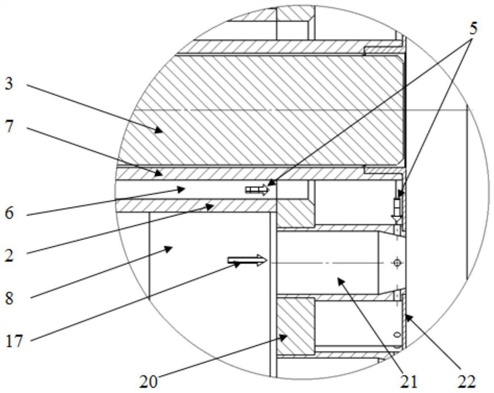
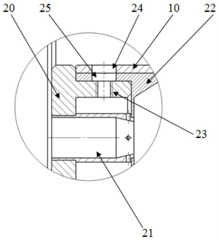
[0035] Such as Figure 1-Figure 9 As shown, a humidification micro-mixed burner, the average temperature of the burner outlet 12 is 1500°C, the average temperature of the inlet of the humidified air 18 is 300°C, the water vapor volume dilution rate is 0.15, including the burner top cover 1, several micro Mixing nozzle 21, air distribution cavity 8, fuel distribution cavity 6, positioning front end cover 20, positioning rear end cover 22, flame tube 10, casing 15 and electric igniter 3, at the center of the burner top cover 1 A through hole is opened, and the electric igniter 3 is installed in the through hole, and a fuel distribution cavity 6 and an air distribution cavity 8 arranged co...


PUM


Abstract

The invention provides a humidifying micro-mixing burner which comprises a burner top cover, a plurality of micro-mixing nozzles, an air distribution cavity, a fuel distribution cavity, a positioning front end cover, a positioning rear end cover, a flame tube, a cartridge receiver and an electric igniter, wherein a through hole is formed in the center of the burner top cover, the fuel distribution cavity and the air distribution cavity are formed in the burner top cover, and an air inlet and a fuel inlet are formed in the burner top cover; and the positioning front end cover is fixed to the tail end of the isolation inner wall, the positioning rear end cover is fixed to the tail end of the wall of the through hole, a plurality of positioning holes are evenly formed in each of the positioning front end cover and the positioning rear end cover, the positioning rear end cover is arranged on the positioning front end cover in a sleeved mode, one end of the flame tube is arranged on the positioning rear end cover in the sleeved mode, and one micro-mixing nozzle is mounted on each pair of positioning holes in one-to-one correspondence between the positioning front end cover and the positioning rear end cover. By using humidifying micro-mixing burner disclosed by the invention, a flame temperature peak value and the size of a high-temperature area are controlled, so that the residence time of flue gas in the high-temperature area is shortened, and low emission of NOx in a high-temperature and high-pressure environment is achieved.

Description

technical field [0001] The invention belongs to the technical field of low-nitrogen combustion, and in particular relates to a humidification and micro-mixing burner. Background technique [0002] In order to improve the efficiency of the energy utilization system, the design temperature rise of the flue gas in the burner is getting higher and higher, but the distribution of the formed high-temperature flue gas is conducive to the large-scale generation of NOx, especially in the field of gas turbines, the operating pressure of the flue gas in the burner It also increases with the increase of unit efficiency and temperature rise. When the temperature of the flame zone is higher than 1900K, the NOx generation rate and the flue gas pressure are roughly in a relationship with a power exponent of 0.5 times. As the pollutant emission indicators become more and more stringent, the traditional burner can no longer meet the pollutant emission requirements under the above working cond...

Claims


Application Information

Patent Timeline
Patent Type & Authority Applications(China)
IPC IPC(8): F23R3/02F23R3/28F23D14/22F23D14/48F23D14/46F23L7/00
CPCF23R3/02F23R3/28F23D14/22F23D14/48F23D14/46F23L7/005F23R2900/03043
Inventor 邢畅邱朋华刘栗胡启明刘健于欣沈闻凯吕亚锦卢成陈希叶张林瑶赵义军孙绍增
Owner HARBIN INST OF TECH
Why Eureka
Try Eureka