Turning conveying track adapting to rapid heating steel billet manufacturing

A transmission track and rapid heating technology, which is applied in the field of round steel processing, can solve the problems that round steel cannot realize automatic turning and reversing, serious waste of site resources, and limited space, so as to reduce the required length of the workshop and reduce the occupied area. Large area, flexible effect

Pending Publication Date: 2021-05-28
宁波恒胜新材料科技有限公司
View PDF0 Cites 1 Cited by
  • Summary
  • Abstract
  • Description
  • Claims
  • Application Information

AI Technical Summary

Problems solved by technology

[0002] During the processing of steel pipes, the round steel needs to be put into the walking furnace for high temperature heating, and then transported to the next process through the transmission track. Because the length of the round steel itself is long, and the equipment used to process the round steel is also Larger, when the round steel passes through the high-temperature furnace, the round steel is conveyed to the next few processes through a straight transmission track to complete a series of processing procedures. In this way, the path spanning in the same direction is longer, and the round steel in the transmission process Therefore, the site is very limited, the site resources are seriously wasted, and there is a problem of high cost
In addition, if the round steel is transported by a right-angle U-turn machine, there are problems of long time and low efficiency

Method used


Image

  • Turning conveying track adapting to rapid heating steel billet manufacturing
  • Turning conveying track adapting to rapid heating steel billet manufacturing
  • Turning conveying track adapting to rapid heating steel billet manufacturing

Examples


Embodiment Construction

[0031] The present invention will be further described below in conjunction with the accompanying drawings.

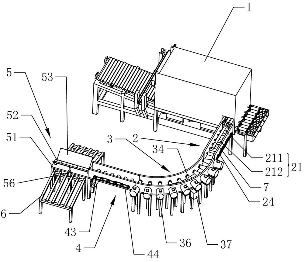
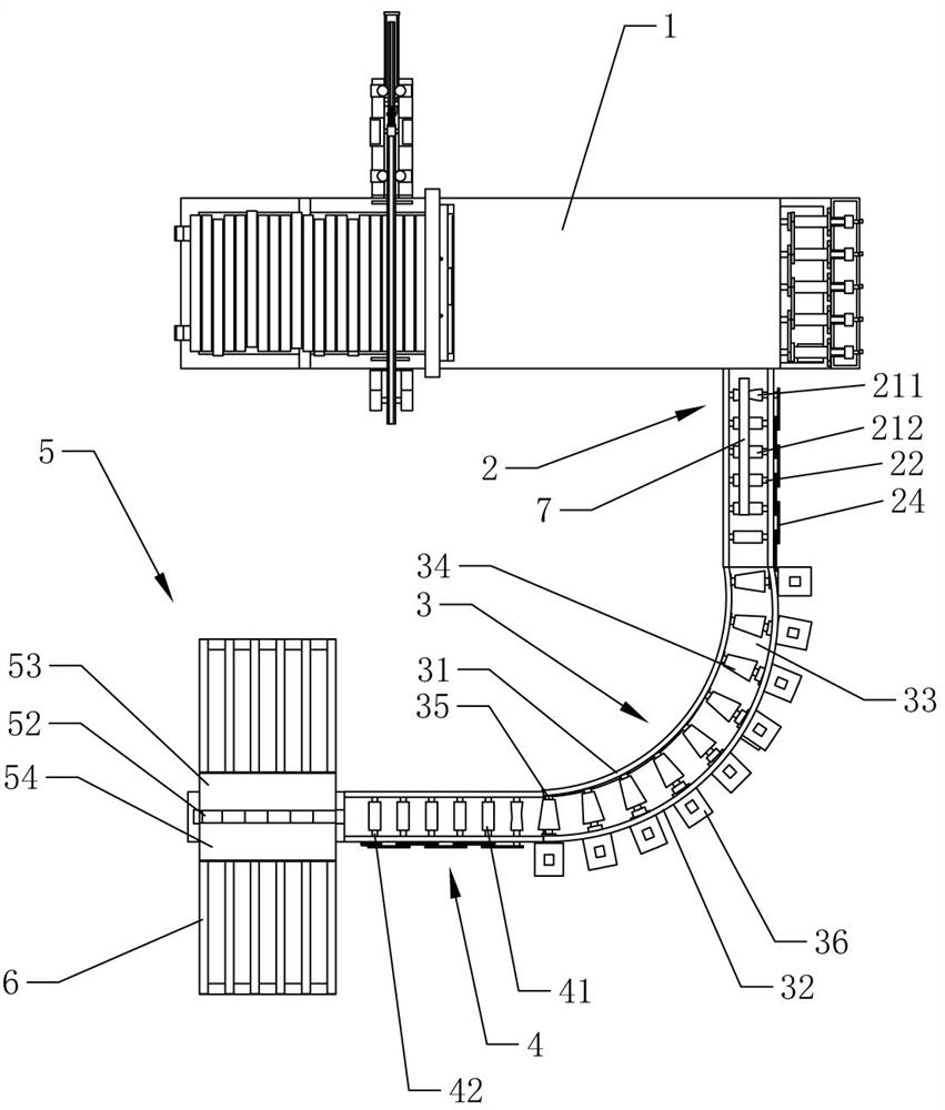
[0032] A turning transmission track suitable for rapid heating billets, such as figure 1 and figure 2 As shown, a walking furnace 1 is included, and the discharge port of the walking furnace 1 is connected with a front straight track 2, an arc-shaped transmission track 3 and a rear straight track 4 in sequence, and a shunt assembly 5 is arranged at the exit of the rear straight track 4. After the round steel 7 heated at high temperature in the walking furnace 1 is sent out from the discharge port, it is transported successively through the front straight track 2, the arc-shaped transmission track 3 and the back straight track 4, and finally the round steel 7 is sequentially carried out in the shunt assembly 5. Divide flow to realize double-track synchronous processing.

[0033] Such as figure 1 , figure 2 and Figure 5As shown, several front rollers 21 are seque...


PUM


Abstract

The invention discloses a turning conveying track adapting to rapid heating steel billet manufacturing. The turning conveying track comprises a stepping furnace, an arc-shaped conveying track is arranged at a discharging opening of the stepping furnace and comprises an arc-shaped inner wall and an arc-shaped outer wall, and an arc-shaped channel is formed between the arc-shaped inner wall and the arc-shaped outer wall. Multiple conical rollers are sequentially arranged in the arc-shaped channel along the arc-shaped conveying track and rotationally connected to the arc-shaped conveying track through rotating shafts, the arc-shaped conveying track is provided with a driving mechanism, the driving mechanism drives the rotating shafts to rotate, the ends, close to the arc-shaped inner wall, of the conical rollers are small ends, the ends, close to the arc-shaped outer wall, of the conical rollers are large ends, and the diameters of the conical rollers are gradually reduced from the large ends to the small ends. The turning conveying track has the following advantages and effects that in the scheme, a new mechanical structure is utilized, the arc-shaped conveying track is adopted to realize conveying reversing, the overall length of conveying is reduced, the length required by a plant can be greatly reduced, the turning conveying track has the effects of reducing the occupied area, saving site resources and effectively reducing the cost, and production efficiency is quite high.

Description

technical field [0001] The invention relates to the technical field of round steel processing, in particular to a turning transmission track adapted to the production of rapidly heating billets. Background technique [0002] During the processing of steel pipes, the round steel needs to be put into the walking furnace for high temperature heating, and then transported to the next process through the transmission track. Because the length of the round steel itself is long, and the equipment used to process the round steel is also Larger, when the round steel passes through the high-temperature furnace, the round steel is conveyed to the next few processes through a straight transmission track to complete a series of processing procedures. In this way, the path spanning in the same direction is longer, and the round steel in the transmission process Automatic turning and reversing cannot be realized in the system, therefore, the site is very limited, the site resources are ser...

Claims


Application Information

Patent Timeline
Patent Type & Authority Applications(China)
IPC IPC(8): F27B9/39
CPCF27B9/39
Inventor 王强高
Owner 宁波恒胜新材料科技有限公司
Why Eureka
Try Eureka