Electrical measurement sample rod for piston type pressure bag

A pressure pack, piston-type technology, applied in the field of electrical measurement, can solve the problems of limited operation space, large pin damage, low measurement efficiency, etc., and achieve the effects of good air tightness, high measurement accuracy, and various measurement methods.

Active Publication Date: 2021-05-28
HEFEI INSTITUTES OF PHYSICAL SCIENCE - CHINESE ACAD OF SCI
View PDF13 Cites 0 Cited by
  • Summary
  • Abstract
  • Description
  • Claims
  • Application Information

AI Technical Summary

Problems solved by technology

As a result, there are two main problems in the measurement: the thermal connection and the vacuum of the sample chamber.
There are mainly two problems. Second, the weight of the piston pressure bag itself is very heavy compared with the general sample holder. The PPMS sample chamber can just put down the pressure bag, and the operating space is very limited. This requires the clamping force of the fixture. Very high, often careless operation, the pressure bag slips in the sample chamber, which will cause great damage to the built-in measurement pins of the PPMS sample chamber. Once hit, the pins will be smashed crookedly, and the repair cost is very expensive. The whole measurement system needs to be repaired for more than half a month , there is a great risk
Second, the built-in measurement system measures the sample in the pressure bag, and can only measure one sample at a time. The measurement efficiency is lower than that of the external system. Due to the limitation of the built-in measurement system, users sometimes need some special measurement requirements, and PPMS cannot meet these requirements.
Now universities and research institutes are very nervous about measuring machines, which is undoubtedly a big shortcoming

Method used


Image

  • Electrical measurement sample rod for piston type pressure bag
  • Electrical measurement sample rod for piston type pressure bag
  • Electrical measurement sample rod for piston type pressure bag

Examples


Embodiment Construction

[0028] The following will clearly and completely describe the technical solutions in the embodiments of the present invention with reference to the accompanying drawings in the embodiments of the present invention. Obviously, the described embodiments are only some, not all, embodiments of the present invention. Based on the embodiments of the present invention, all other embodiments obtained by persons of ordinary skill in the art without making creative efforts belong to the protection scope of the present invention.

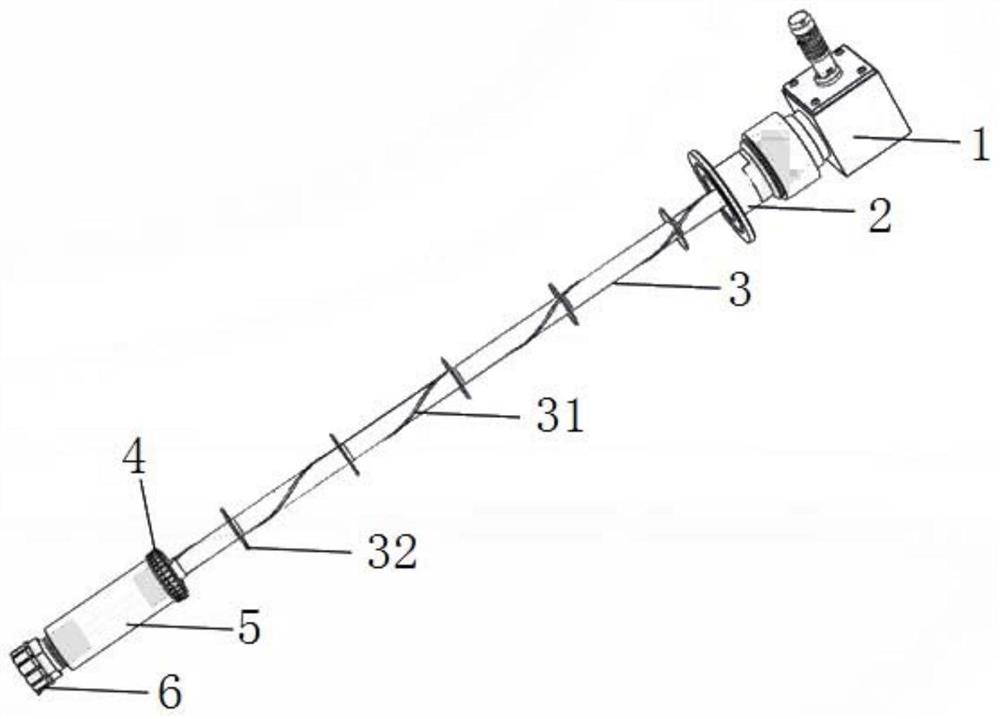
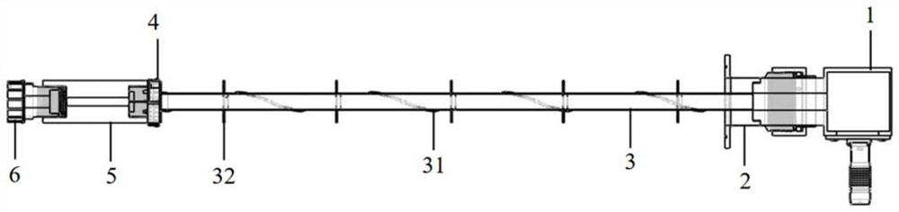
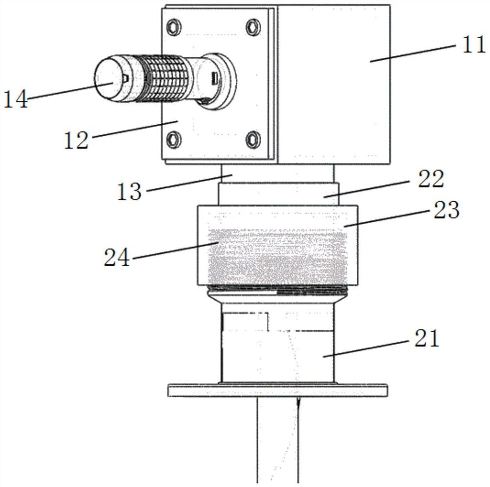
[0029] see Figure 1-5 , in an embodiment of the present invention, an electrical measurement sample rod for a piston-type pressure pack, including a connecting pipe 3 fixedly connected to the pressure pack 5, and a test adapter 1 fixedly connected to the end of the connecting pipe 3 away from the pressure pack 5 The test adapter 1 is connected with an adjustment part 2, the test adapter 1 includes an adapter 11, a connector 12, a connection seat 13, and an ex...


PUM


Abstract

The invention discloses an electrical measurement sample rod for a piston type pressure bag. The sample rod comprises a connecting pipe fixedly connected with the pressure bag, one end, far away from the pressure bag, of the connecting pipe is fixedly connected with a test switching part, and the test switching part is connected with an adjusting part; the test switching part comprises an adapter, and the adapter is provided with a connecting seat and an external connector; the adjusting part comprises a sliding sleeve connected with the connecting seat; and the connecting pipe comprises a hollow pipe and a wire arranged in the axis direction of the hollow pipe, and the two ends of the wire are communicated with the pressure bag and the external connector respectively. By arranging the sample rod with an adjustable length, when the length of the pressure bag changes, an up-and-down distance between the test switching part and the sliding sleeve can be adjusted to ensure that a sample bottom bracket at the bottom of the sample rod is tightly contacted with the bottom end of the inner wall of a measuring system, and good heat-conducting property is ensured, so that the measuring precision is high and the efficiency is high. And the air tightness of the sample rod is very good.

Description

technical field [0001] The invention relates to the field of electrical measurement, in particular to an electrical measurement sample rod for a piston pressure pack. Background technique [0002] The piston pressure bag is a cylindrical structure, with screws at both ends. The sample is sealed in a Teflon tube filled with high-pressure oil, and then placed in the cylinder. One end is led out with a wire and fixed with screws; The Teflon tube is pressurized through the pressure transmission method of screwing, and the high-pressure oil is squeezed to obtain pressure. The more the screw is screwed in, the greater the pressure obtained. The length of the piston pressure bag is different under different pressures like this. Therefore, when the physical property measurement system (Physical Property Measurement System, PPMS) designed by Quantum Design Company performs electrical measurement under pressure, there is a problem. The length of the pressure bag is different, and the...

Claims


Application Information

Patent Timeline
IPC IPC(8): G01N33/00G01N27/00
CPCG01N33/00G01N27/00Y02E30/30
Inventor 张勇张警蕾屈哲韩慧皮雳
Owner HEFEI INSTITUTES OF PHYSICAL SCIENCE - CHINESE ACAD OF SCI
Why Eureka
Try Eureka