
Control device and method of circuit system

A circuit system and control device technology, applied in the field of circuit systems, can solve problems such as power loss, energy waste, and high circuit costs

Pending Publication Date: 2021-05-28
深圳华兴新能源科技有限公司
View PDF0 Cites 0 Cited by
  • Summary
  • Abstract
  • Description
  • Claims
  • Application Information

AI Technical Summary

Problems solved by technology

[0003] However, some existing circuit systems or devices continue to work when they do not need to work, and there is a lot of waste of energy
There are also some circuit systems or devices that control all circuits through the processor to enter the sleep state when they do not need to work, and at the same time the processor enters the standby state. Some module circuits or devices in irrelevant circuits will not have low power consumption mode, such as resistors, capacitors, inductors, transistors, diodes and other components, some chips, etc., the equivalent resistance of these devices will cause power loss
In addition, even if these circuits that have nothing to do with wake-up signal generation have a low-power mode, the energy consumed by these circuits in low-power sleep is meaningless when the system does not need to work.
Moreover, in order to reduce the standby power consumption of the system, no matter whether it is a circuit related to the wake-up signal or not, a chip or device with a low power consumption mode function must be selected, resulting in a higher circuit cost

Method used


Image

  • Control device and method of circuit system
  • Control device and method of circuit system
  • Control device and method of circuit system

Examples


Embodiment Construction

[0023] The following will clearly and completely describe the technical solutions in the embodiments of the present invention with reference to the accompanying drawings in the embodiments of the present invention. Obviously, the described embodiments are only some, not all, embodiments of the present invention. The components of the embodiments of the invention generally described and illustrated in the figures herein may be arranged and designed in a variety of different configurations. Accordingly, the following detailed description of the embodiments of the invention provided in the accompanying drawings is not intended to limit the scope of the claimed invention, but merely represents selected embodiments of the invention. Based on the embodiments of the present invention, all other embodiments obtained by those skilled in the art without making creative efforts belong to the protection scope of the present invention.

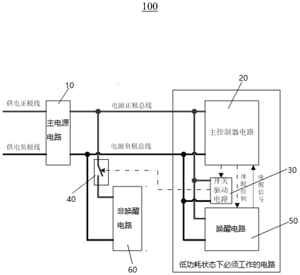
[0024] see figure 1 The present invention provides ...


PUM


Abstract

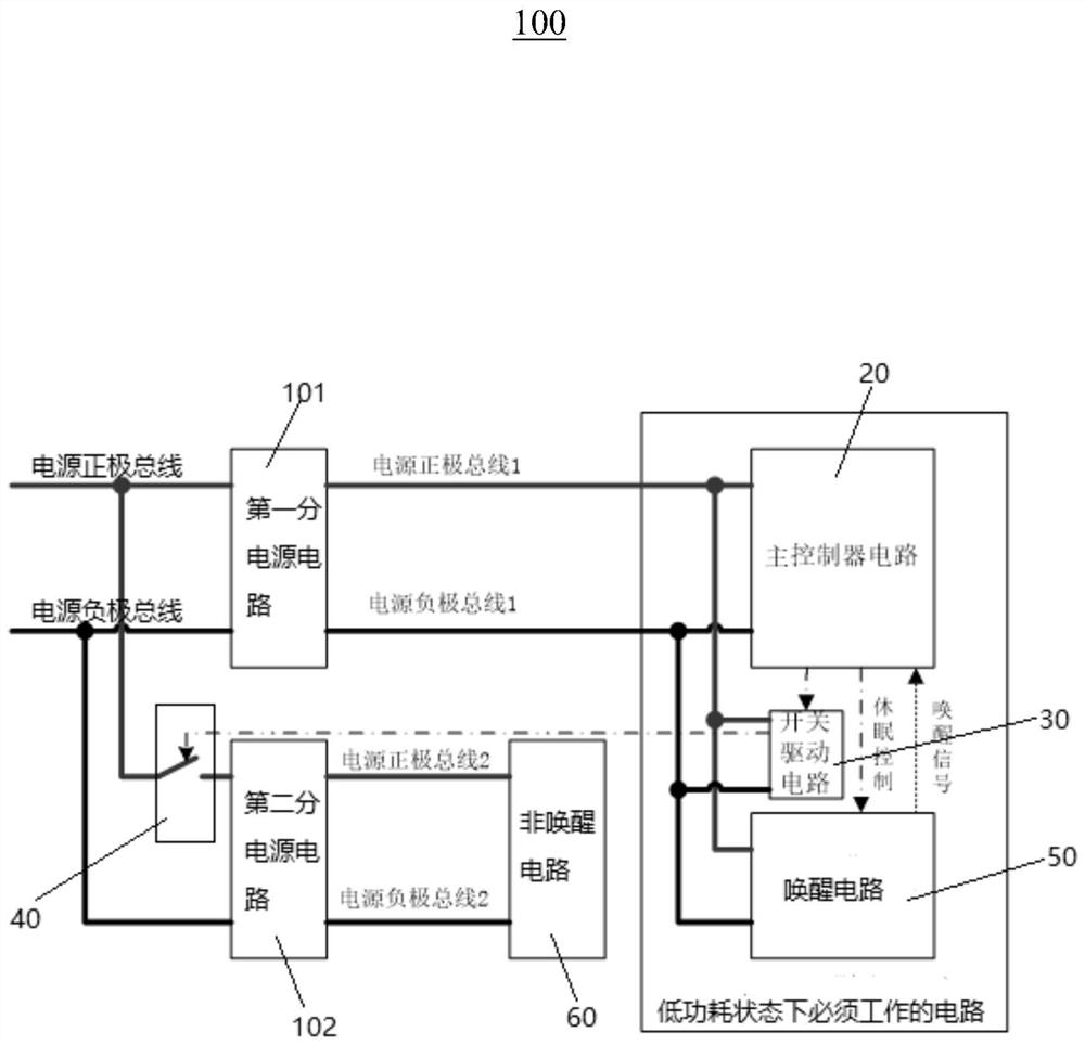
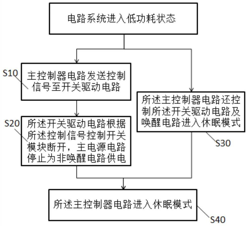
The invention provides a control device of a circuit system. The control device comprises a main power supply circuit, a main controller circuit, a switch driving circuit, a switch module, a wake-up circuit and a non-wake-up circuit, wherein the main power supply circuit is respectively connected with the main controller circuit, the switch driving circuit and the wake-up circuit, the main power supply circuit is also connected with the non-wake-up circuit through the switch module, and when a circuit system enters a low-power-consumption state, the main controller circuit sends a control signal to the switch driving circuit, the switch driving circuit controls the switch module to be switched off according to the control signal, and the main power supply circuit stops supplying power to the non-wake-up circuit. The invention further provides a control method of the circuit system. According to the control device and method of the circuit system, when the circuit system enters the low-power-consumption state, the non-wake-up circuit is completely powered off to achieve zero power consumption of the circuit, and the devices and chips of the non-wake-up circuit do not need to be selected from devices and chips in a sleep mode, so that the system cost is lower.

Description

【Technical field】 [0001] The invention relates to the technical field of circuit systems, in particular to a control device and method for a circuit system. 【Background technique】 [0002] With the development and progress of society, the problems caused by environmental pollution and energy waste have become more and more prominent, and energy conservation and emission reduction have attracted more and more attention from the state and enterprises. In electronics, circuits, and electrical systems, there are many applications that are necessary for low power consumption and low loss of the system, such as: energy storage base station battery management system, electric vehicle or electric bicycle battery protection board management system, printer system, etc. When the battery is installed but the system load is not connected or there is no external command to perform operations, it should enter the low power consumption mode. [0003] However, some existing circuit systems...

Claims


Application Information

Patent Timeline
IPC IPC(8): G05B19/042
CPCG05B19/0423G05B2219/24024
Inventor 秦宗伟孙怀兵彭澎
Owner 深圳华兴新能源科技有限公司
Learn More