Supercharge Your Innovation With Domain-Expert AI Agents!

A Transient Response Linear Regulator

A linear regulator and transient response technology, applied in instruments, control/regulation systems, and electrical variables, etc., can solve the problems of poor output voltage stability, untimely response, and high power consumption, reducing output swing, Save area and restore fast results

Active Publication Date: 2022-07-19
INST OF MICROELECTRONICS CHINESE ACAD OF SCI
View PDF4 Cites 0 Cited by
  • Summary
  • Abstract
  • Description
  • Claims
  • Application Information

AI Technical Summary

Problems solved by technology

[0005] In view of the above analysis, the embodiment of the present invention aims to provide an instantaneous response linear voltage regulator to solve the problems of high power consumption, poor output voltage stability and untimely response of the existing linear voltage regulator

Method used


Image

  • A Transient Response Linear Regulator
  • A Transient Response Linear Regulator
  • A Transient Response Linear Regulator

Examples


Embodiment Construction

[0061] The preferred embodiments of the present invention are specifically described below with reference to the accompanying drawings, wherein the accompanying drawings constitute a part of the present application, and together with the embodiments of the present invention, are used to explain the principles of the present invention, but are not used to limit the scope of the present invention.

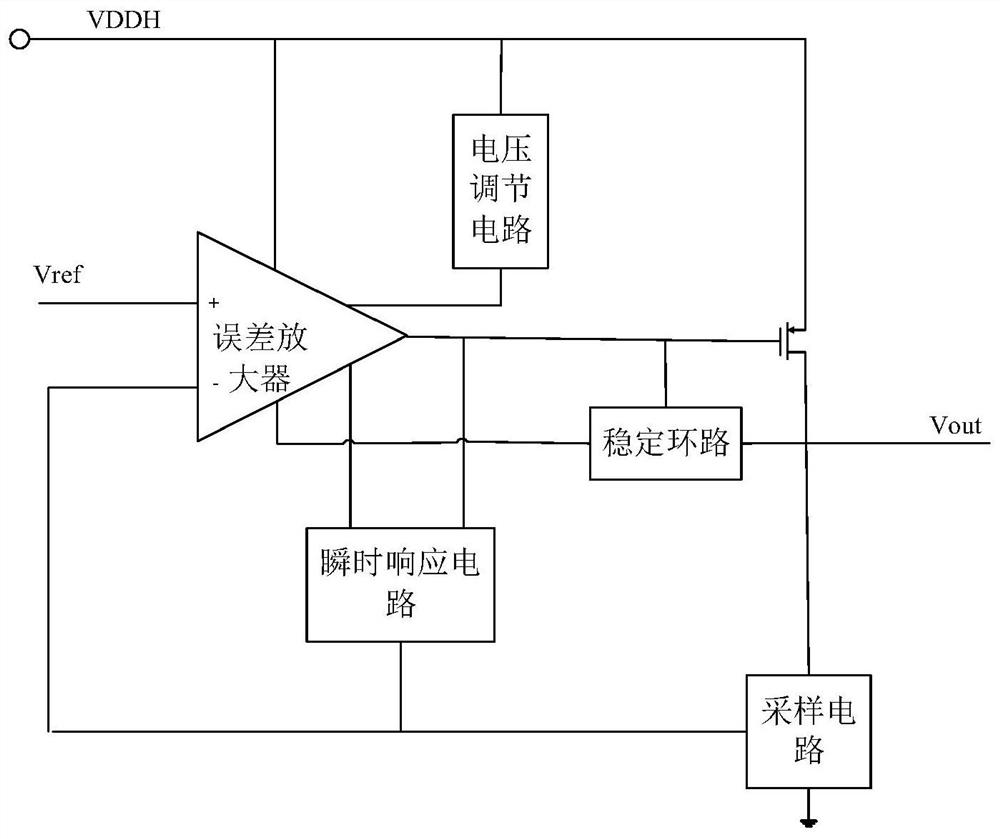
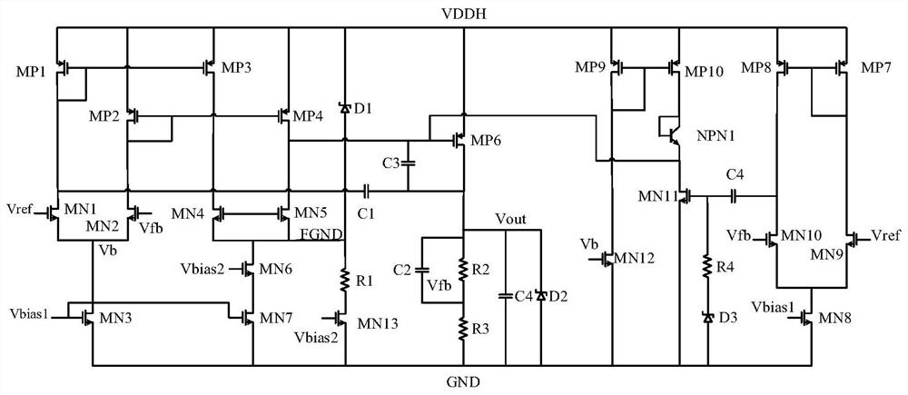
[0062] A specific embodiment of the present invention discloses an instantaneous response linear voltage regulator, the schematic diagram is as follows figure 1 As shown, the circuit connection diagram is as follows figure 2 As shown, it includes: an error amplifier, a power switch tube MP6, a voltage regulation circuit, an instantaneous response circuit and a stabilization loop.

[0063] the error amplifier for the received reference voltage V ref and the sampling voltage V fb Perform gain amplification on the difference of , to obtain the difference voltage after gain amplificat...


PUM


Abstract

The invention relates to an instantaneous response linear voltage stabilizer, belongs to the technical field of integrated circuit design, and solves the problems of high power consumption, poor output voltage stability and untimely response of the linear voltage stabilizer in the prior art. The voltage stabilizer includes an error amplifier, a power switch tube, a voltage regulation circuit, an instantaneous response circuit and a stabilization loop; the error amplifier is used to amplify the difference between the received reference voltage and the sampled voltage, and obtain the difference after gain amplification voltage; and, for outputting a feedback voltage to an instantaneous response circuit according to the change of the received sampling voltage; a power switch tube for adjusting the load current according to the difference voltage after gain amplification, and outputting the output voltage of the linear regulator according to the load current ;Instantaneous response circuit, according to the feedback voltage and the sampling voltage to control whether the instantaneous response circuit and the power switch tube form a charge and discharge loop, so that the load current of the power switch tube instantaneously responds to the change of the output voltage of the linear regulator.

Description

technical field [0001] The invention relates to the technical field of integrated circuit design, in particular to an instantaneous response linear voltage regulator. Background technique [0002] With the rapid development of modern electronic devices, electronic devices have become an indispensable part of people's daily life and work. The power management circuit provides stable and reliable voltage to the electronic equipment by converting the external power supply, and is an important part of the electronic equipment. Linear regulator is a classic power management circuit, which has been widely used in many advanced portable devices and battery-powered systems. It has the advantages of simple structure, high conversion efficiency, high integration, and low noise. [0003] Existing linear regulators without off-chip capacitors depend on the fast response of the power switch to change the load. When the load changes, the power switch tube cannot quickly adjust its own l...

Claims


Application Information

Patent Timeline
Patent Type & Authority Patents(China)
IPC IPC(8): G05F3/26
CPCG05F3/26
Inventor 吴飞彤蔡小五刘海南赵海涛卜建辉赵发展
Owner INST OF MICROELECTRONICS CHINESE ACAD OF SCI
Features
  • R&D
  • Intellectual Property
  • Life Sciences
  • Materials
  • Tech Scout
  • Unparalleled Data Quality
  • Higher Quality Content
  • 60% Fewer Hallucinations
Learn More