Cable take-up and pay-off device

A retractable device and cable technology, which can be used in cable laying equipment, electronic waste recycling, and the layout of paper reels/photosensitive drums, etc. It can solve the problems of high cable weight, easy deformation of cables, and difficulty in laying

Active Publication Date: 2021-05-28
沂蒙电缆有限公司
View PDF8 Cites 1 Cited by
  • Summary
  • Abstract
  • Description
  • Claims
  • Application Information

AI Technical Summary

Problems solved by technology

[0005] The technical problem to be solved in the present invention is to provide a cable retracting device, one of which is to have the characteristics of quickly retracting and retracting the cable, and to solve the problem that when the cable is laid, the staff usually pulls the cable manually. The high weight brings great difficulties to manual laying, which leads to the problem of low cable laying efficiency; another purpose is to solve the problem that the cables are prone to deformation due to the long-term binding of the cables outside the cable rack. If the cable is not straightened, it is easy to increase the difficulty of cable laying, resulting in the problem of reducing the work efficiency of cable laying, so as to achieve the effect of improving the work efficiency of cable laying

Method used


Image

  • Cable take-up and pay-off device
  • Cable take-up and pay-off device
  • Cable take-up and pay-off device

Examples


Embodiment 1

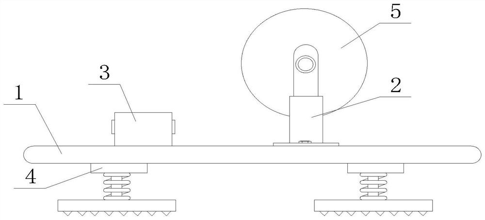
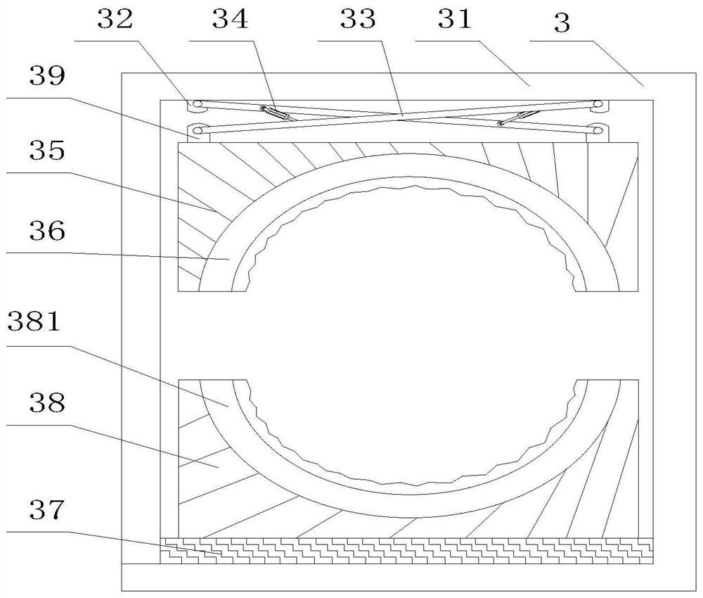
[0037] Such as Figure 1-7 As shown, the present invention provides a cable retractable device, including a cable workbench 1, the top of the cable workbench 1 is fixedly connected with a support device 2, and the top of the cable workbench 1 is fixedly connected with a cable on the left side away from the support device 2 Straightening device 3, the cable straightening device 3 includes a cable straightening box 31, the top of the cable straightening box 31 inner wall is fixedly connected with a No. 1 fixed buckle 32, and the front of the No. 1 fixed buckle 32 is movably connected with a cross link 33. The front of connecting rod 33 is movably connected with cylinder 34, and one end of cross-connecting rod 33 is movably connected with No. 2 fixed buckle 39, and the bottom of No. 2 fixed buckle 39 is fixedly connected with movable plate 35, and the bottom of movable plate 35 is fixedly connected with No. 1 arc Shaped plate 36, the bottom of No. 1 arc-shaped plate 36 is provide...

Embodiment 2

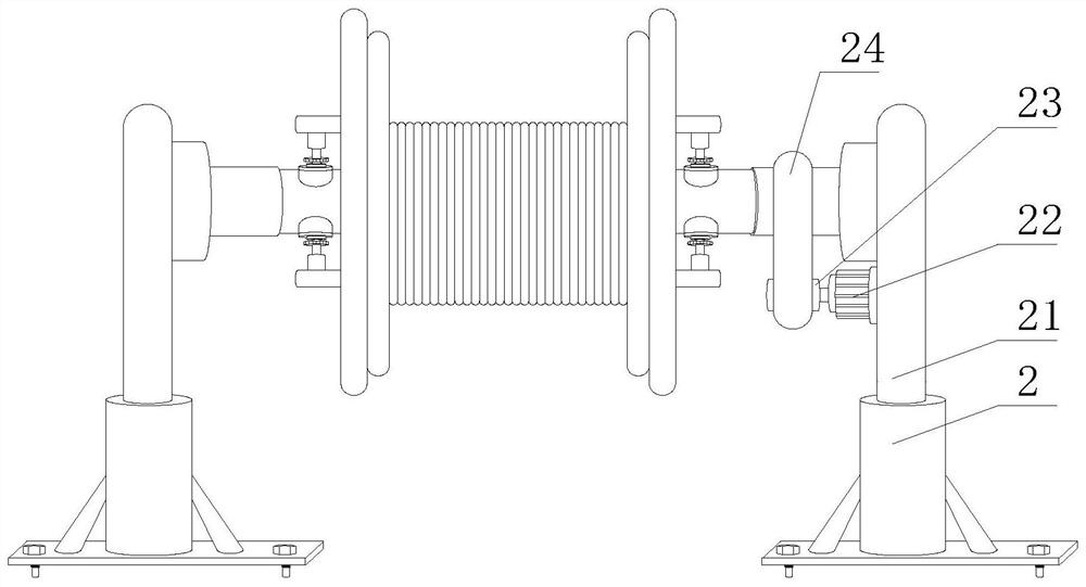
[0042] Such as Figure 1-7 As shown, on the basis of Embodiment 1, the present invention provides a technical solution: the number of supporting devices 2 is two, and the two supporting devices 2 are symmetrically arranged on the top of the cable workbench 1, and the two supporting devices 2 include Support plate 28, the top of support plate 28 is fixedly connected with electric lifting column 21, and the both sides of electric lifting column 21 is fixedly connected with support column 29, and the bottom of support column 29 is fixedly connected with the top of support plate 28, and support column 29 has increased The force bearing area between the bottom of the electric lifting column 21 and the top of the support plate 28 makes the electric lifting column 21 more stable and reliable. One side of the electric lifting column 21 is fixedly connected with a No. The side is fixedly connected with an electric telescopic rod 26, and one end of the electric telescopic rod 26 is fixe...

Embodiment 3

[0044] Such as Figure 1-7 As shown, on the basis of Embodiment 1, the present invention provides a technical solution: preferably, one side of the electric lifting column 21 is fixedly connected with a DC drive motor 22, and the output end of the DC drive motor 22 is fixedly connected with a rotating shaft 23, The outer wall of the rotating shaft 23 is movably socketed with crawler belts 24 , and the inner wall at the top of the crawler belts 24 is movably socketed on the outer wall of the electric telescopic rod 26 to start the DC drive motor 22 , and at the same time the DC drive motor 22 drives the rotating shaft 23 to rotate, while the rotating shaft 23 drives the crawler belt 24 to rotate , crawler belt 24 simultaneously drives electric telescoping bar 26, fixed block 27, cable rack 5 No. 1 turntable 25 rotations, makes cable downwards and breaks away from cable rack 5 quickly, avoids when laying cable, usually the staff adopts manual pull cable, because The high weight ...


PUM


Abstract

The invention discloses a cable take-up and pay-off device, and relates to the technical field of cables, the cable take-up and pay-off device comprises a cable workbench, the top of the cable workbench is fixedly connected with two supporting devices, the two supporting devices are symmetrically arranged at the top of the cable workbench, and the two supporting devices comprise supporting plates. By adopting the combined arrangement of the direct-current driving motor, the rotating shaft, the crawler belt, the first turntable, the electric telescopic rod, the fixed block and the cable rack, the direct-current driving motor is started and drives the rotating shaft, the crawler belt, the first turntable, the electric telescopic rod, the fixed block and the cable rack to rotate, so that a cable is quickly separated from the cable rack, the problem that when a cable is laid, a worker usually pulls the cable manually, due to the fact that the weight of the cable is high, great difficulty is brought to manual laying, and the cable laying efficiency is low is avoided, the work time of the worker is shortened, and the cable winding and unwinding work efficiency is improved.

Description

technical field [0001] The invention relates to a cable device, relates to the technical field of cables, in particular to a cable retracting device. Background technique [0002] A cable is made of one or more mutually insulated conductors and an outer insulating protective layer. It is a wire that transmits power or information from one place to another. The cable has the characteristics of internal energization and external insulation, and is widely used in power systems. , information transmission, instrumentation systems and other industries. There are following problems at prior art: [0003] 1. When laying the cable, the staff usually pull the cable manually. Due to the high weight of the cable, it brings great difficulties to the manual laying, resulting in the problem of low cable laying efficiency. [0004] 2. Since the cables are bound on the outside of the cable rack for a long time, the cables are prone to deformation. If the cables are not straightened, it is...

Claims


Application Information

Patent Timeline
Patent Type & Authority Applications(China)
IPC IPC(8): H02G1/06H02G11/02
CPCH02G1/06H02G11/02Y02W30/82
Inventor 罗正友
Owner 沂蒙电缆有限公司
Why Eureka
Try Eureka