Power compensation type rare earth permanent magnet motor and control method

A rare-earth permanent magnet motor and power compensation technology, which is applied in the direction of motor generator control, electronic commutation motor control, control system, etc., can solve the problems of short life of electrolytic capacitors, delay of speed adjustment, and hysteresis of adjustment signals, etc., to achieve Prevent demagnetization, increase cooling time, and ensure efficient operation

Inactive Publication Date: 2021-05-28
苏州全光光伏科技有限公司
View PDF0 Cites 0 Cited by
  • Summary
  • Abstract
  • Description
  • Claims
  • Application Information

AI Technical Summary

Problems solved by technology

[0002] With the development of science and technology, various fields of industry in our country have made rapid progress. Due to the advantages of high efficiency, high precision and good quality, permanent magnet synchronous motors are now used as core power components in many aspects, and in many environments. Therefore, the stability of the motor operation is very important. At present, the electrolytic capacitors used to control the permanent magnet motor have short life, poor reliability and low system power factor. Dynamic compensation is carried out in the middle, so that the permanent magnet motor still has a high power factor when it is continuously in a high-load operation state, ensuring the safe and efficient operation of the motor
[0003] Most of the traditional rare earth permanent magnet motors drive the permanent magnet motor through a matrix converter to adjust the speed, changing the input reactive power factor. During the adjustment process, it is easy to have a speed adjustment delay and adjustment deviation, resulting in the motor running state always being in the system. In the hysteresis zone of the adjustment, the adjustment signal has hysteresis. In addition, in the process of power compensation, it is impossible to perform multi-level compensation and real-time dynamic compensation by monitoring the operating power of the system, and the compensation effect is poor.

Method used


Image

  • Power compensation type rare earth permanent magnet motor and control method
  • Power compensation type rare earth permanent magnet motor and control method
  • Power compensation type rare earth permanent magnet motor and control method

Examples


Embodiment Construction

[0040] In order to more clearly understand the above objects, features and advantages of the present invention, the present invention will be further described in detail below in conjunction with the accompanying drawings and specific embodiments. structure, so it only shows the configuration related to the present invention, and it should be noted that, in the case of no conflict, the embodiments in the present application and the features in the embodiments can be combined with each other.

[0041] In the description of the present application, it should be understood that the terms "center", "longitudinal", "transverse", "upper", "lower", "front", "rear", "left", "right", " The orientation or positional relationship indicated by "vertical", "horizontal", "top", "bottom", "inner", "outer", etc. is based on the orientation or positional relationship shown in the drawings, and is only for the convenience of describing the present application and Simplified descriptions do not ...


PUM


Abstract

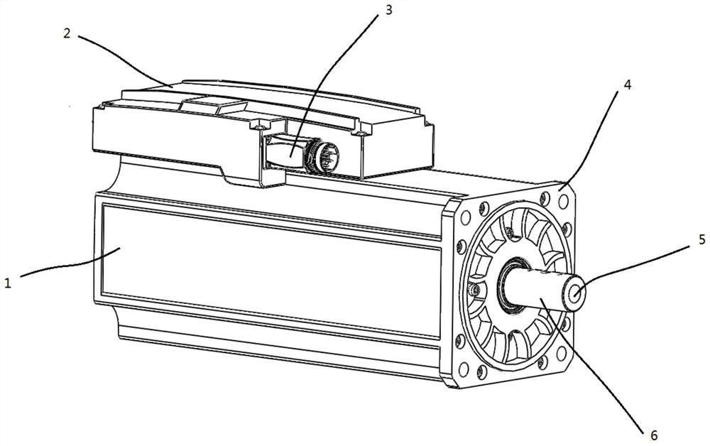
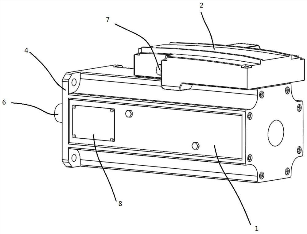
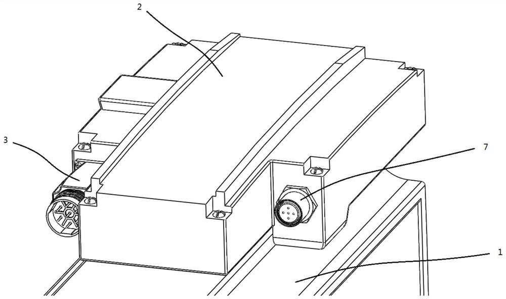
The invention relates to a power compensation type rare earth permanent magnet motor and a control method. The power compensation type rare earth permanent magnet motor comprises a shell and a power compensation assembly arranged at the top of the shell. A plurality of stators are arranged on the inner wall of the shell, the stators are distributed around the inner wall of the shell at intervals, and excitation coils are arranged on the outer sides of the stators; a rotor is connected in the shell in a matched mode in the center line direction, magnetic steel is arranged at one end of the rotor, and a plurality of permanent magnets are arranged on the outer side of the magnetic steel at intervals in the circumferential direction. The power compensation assembly comprises a first compensator and a second compensator, the first compensator and the second compensator are both connected with a current detection mechanism, the first compensator is matched with the second compensator, and a switching mechanism is arranged between the first compensator and the second compensator; the switching mechanism can gate the first compensator or/and the second compensator to operate; and a correction unit is arranged in the power compensation assembly, and the correction unit is provided with a power input end and a power output end.

Description

technical field [0001] The invention relates to a rare earth permanent magnet motor, in particular to a power compensation type rare earth permanent magnet motor and a control method. Background technique [0002] With the development of science and technology, various fields of industry in our country have made rapid progress. Due to the advantages of high efficiency, high precision and good quality, permanent magnet synchronous motors are now used as core power components in many aspects, and in many environments. Therefore, the stability of the motor operation is very important. At present, the electrolytic capacitors used to control the permanent magnet motor have short life, poor reliability and low system power factor. Dynamic compensation is carried out in the middle, so that the permanent magnet motor still has a high power factor when it is continuously in a high-load operation state, ensuring safe and efficient operation of the motor. [0003] Most of the traditio...

Claims


Application Information

Patent Timeline
Patent Type & Authority Applications(China)
IPC IPC(8): H02K11/30H02K1/32H02K1/27H02P21/22
CPCH02K1/2706H02K1/32H02K11/30H02P21/22
Inventor 彭剑辉
Owner 苏州全光光伏科技有限公司
Why Eureka
Try Eureka