
Method for exhaust gas aftertreatment, and exhaust gas aftertreatment system

A technology of exhaust gas post-treatment and exhaust gas pipeline, which is applied in the direction of electronic control of exhaust treatment devices, exhaust treatment, exhaust devices, etc.

Active Publication Date: 2021-05-28
VTESCO TECH GMBH
View PDF10 Cites 0 Cited by
  • Summary
  • Abstract
  • Description
  • Claims
  • Application Information

AI Technical Summary

Problems solved by technology

As a result, even small deviations in one direction or another can cause emissions

Method used


Image

  • Method for exhaust gas aftertreatment, and exhaust gas aftertreatment system
  • Method for exhaust gas aftertreatment, and exhaust gas aftertreatment system

Examples


Embodiment Construction

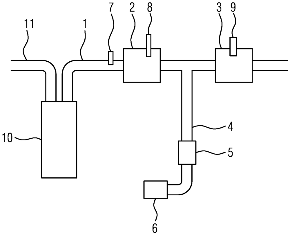
[0047] figure 1 A gasoline engine (spark ignition engine) 10 is schematically shown with an air supply line 11 and an exhaust gas line 1 . Arranged in the exhaust gas line 1 is a first three-way catalytic converter 2 followed by a second three-way catalytic converter 3 . A linear lambda probe 7 is arranged upstream of the first three-way catalytic converter 2 . The first three-way catalytic converter 2 is provided with a NOx sensor 8 arranged in the catalytic converter at 2 / 3 of the length of the catalytic converter.

[0048] The second three-way catalytic converter 3 is located downstream of the first three-way catalytic converter 2 and has a binary lambda probe 9 . Leading into the exhaust gas duct 1 between the two catalytic converters 2 , 3 is a secondary air line 4 , through which secondary air is blown in by means of a secondary air pump 6 and a secondary air valve 5 .

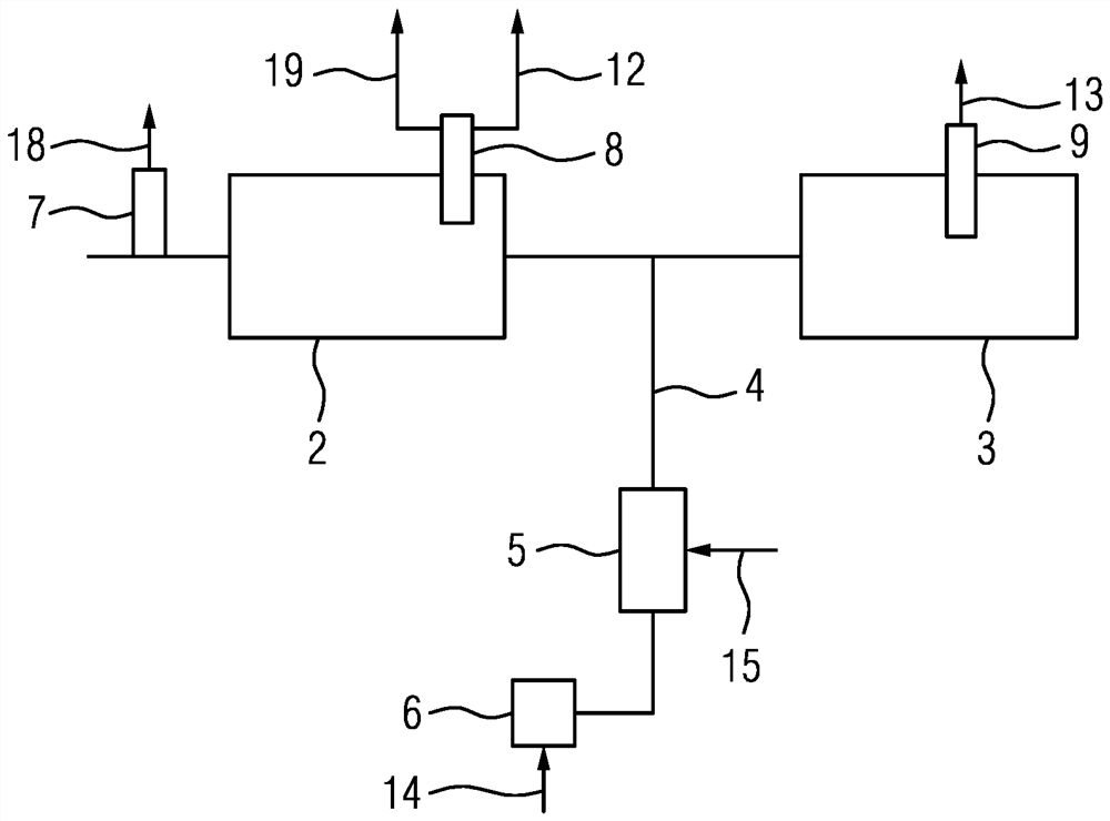
[0049] refer to figure 2 The operation mode of the exhaust gas aftertreatment system described a...


PUM


Abstract

The invention relates to a method for exhaust gas aftertreatment in a petrol engine (10) and to an exhaust gas aftertreatment system. In the method, two catalysts (2.3) arranged in the exhaust gas tract (1) of the petrol engine (10) are operated in different states. A first three-way catalyst (2) is operated in a slightly low-oxygen zone and a second three-way catalyst (3) is operated in a slightly oxygen-rich zone. Furthermore, secondary air is blown into the exhaust gas tract (1) between the two three-way catalysts (2.3). As a result, the output of emissions of the petrol engine (10) can be reduced particularly drastically. The invention further relates to an exhaust gas aftertreatment system.

Description

technical field [0001] The invention relates to a method for aftertreatment of exhaust gas in a gasoline engine and an aftertreatment system of exhaust gas. Background technique [0002] In the case of gasoline engines, a three-way catalytic converter is used for exhaust gas aftertreatment. These catalytic converters convert pollutants, namely hydrocarbons (HC), carbon monoxide (CO) and nitrogen oxides (NOx), into harmless exhaust gas components such as water and carbon dioxide. Certain conditions must exist in a catalytic converter for ideal conversion. Therefore, the temperature of the catalytic converter must be higher than the light-off temperature required for conversion. Furthermore, the reactants must be provided in the correct proportions. This can occur if the amount of oxygen in the exhaust is just sufficient to allow all exhaust components to be oxidized. In this case, refer to the exhaust gas lambda value of lambda = 1.0. [0003] In order to ensure these id...

Claims


Application Information

Patent Timeline
IPC IPC(8): F01N3/10F01N3/30F01N3/32F01N9/00F01N13/00
CPCF01N3/101F01N3/30F01N3/32F01N9/00F01N13/0093F01N2560/025F01N2560/021F01N2560/026F01N2560/14F01N3/22Y02T10/12Y02T10/40F01N3/225F01N2270/00
Inventor G·哈夫特
Owner VTESCO TECH GMBH
Learn More