Cervical vertebra and lumbar vertebra rehabilitation training equipment
A technology for rehabilitation training and lumbar spine, which is applied in the field of cervical spine and lumbar spine rehabilitation training equipment. It can solve the problems of exacerbation of the disease and incorrect exercise methods, and achieve the effect of adjustable swing range and easy recovery of lumbar spine function.
- Summary
- Abstract
- Description
- Claims
- Application Information
AI Technical Summary
Problems solved by technology
Method used
Image
Examples
specific Embodiment approach 1
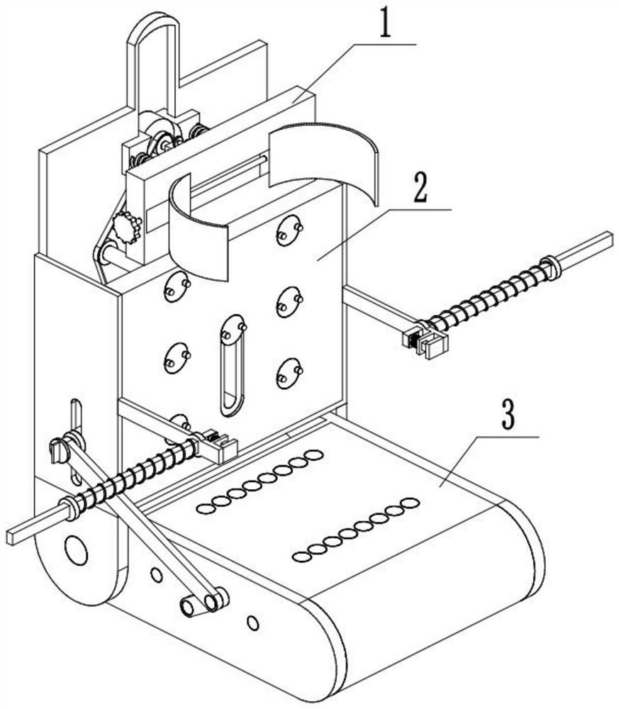
[0031] Combine below Figure 1-15 Describe this embodiment, a cervical spine and lumbar spine rehabilitation training equipment, including a cervical spine rehabilitation assembly 1, a back massage assembly 2, and a lumbar spine rehabilitation assembly 3, and the cervical spine rehabilitation assembly 1 is connected to the back massage assembly 2 , the back massage assembly 2 is connected with the lumbar rehabilitation assembly 3 .
specific Embodiment approach 2
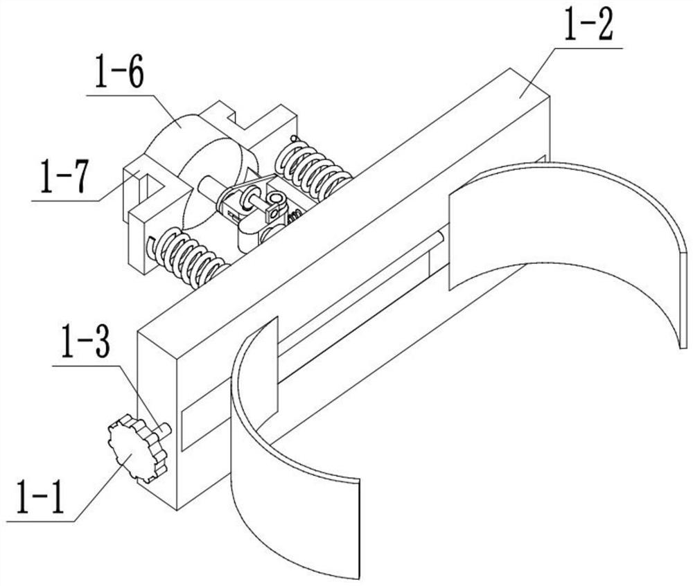
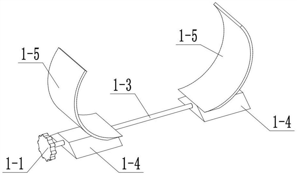
[0033] Combine below Figure 1-15Describe this embodiment, this embodiment will further explain the first embodiment, the cervical spine rehabilitation combination 1 includes a handle I1-1, a rocking frame 1-2, a two-way threaded shaft 1-3, a threaded slider 1-4, a clip Tight claw 1-5, motor I 1-6, motor I bracket 1-7, tension spring 1-8, motor I shaft 1-9, lug I 1-10, lug II 1-11, angle adjustment block 1-12 , handle II 1-13, worm 1-14, worm bracket 1-15, worm gear 1-16, worm gear shaft 1-17, gear 1-18, rack 1-19, rack slider 1-20, spring Ⅰ 1- 21. The rack bracket 1-22, the deflection sliding column 1-23 and the deflection cylinder 1-24, the handle I 1-1 is connected with the bidirectional threaded shaft 1-3, and two bidirectional threaded shafts 1-3 are provided with two Threads with opposite directions of rotation, the two-way threaded shaft 1-3 is rotationally connected with the shaking frame 1-2, the two threaded sliders 1-4 are slidingly connected with the shaking frame...
specific Embodiment approach 3
[0035] Combine below Figure 1-15 This embodiment will be described. This embodiment will further illustrate the first embodiment. The back massage assembly 2 includes a motor I bracket slide rail 2-1, a back plate I 2-2, a side plate 2-3, a back plate II 2-4, Side plate lug 2-5, limit rod 2-6, extension spring 2-7, fixed rod 2-8, electromagnet 2-9, iron block 2-10, spring II 2-11, sprocket I 2-12, Chain 2-13, sprocket Ⅱ2-14, sprocket Ⅲ2-15, rotating rod Ⅰ2-16, massage disc 2-17, rotating rod Ⅱ2-18, cross slider 2-19, cross chute 2-20, spring Fixed block 2-21, spring limit post 2-22, spring III 2-23, knob 2-24, connecting rod sliding post 2-25, threaded shaft 2-26, limit block 2-27 and limit block chute 2-28, the motor I bracket 1-7 is slidingly connected with the motor I bracket slide rail 2-1, the motor I bracket slide rail 2-1 is connected with the backplane I2-2, and the backplane I2-2 is connected with two side panels 2 -3 is connected, the two side plates 2-3 are conne...
PUM
 Abstract
Description
Claims
Application Information
 - R&D
- Intellectual Property
- Life Sciences
- Materials
- Tech Scout
- Unparalleled Data Quality
- Higher Quality Content
- 60% Fewer Hallucinations
Browse by: Latest US Patents, China's latest patents, Technical Efficacy Thesaurus, Application Domain, Technology Topic, Popular Technical Reports.
© 2025 PatSnap. All rights reserved.Legal|Privacy policy|Modern Slavery Act Transparency Statement|Sitemap|About US| Contact US: help@patsnap.com


