Thermal desorption remediation device for soil remediation

A soil remediation and thermal desorption technology, which is applied in the field of thermal desorption repair devices for soil remediation, can solve the problems of uneven heat reception by the soil and limited thermal desorption effect, and achieve the effect of high efficiency and avoiding aggregation

Inactive Publication Date: 2021-06-01
郭文静
View PDF9 Cites 1 Cited by
  • Summary
  • Abstract
  • Description
  • Claims
  • Application Information

AI Technical Summary

Problems solved by technology

However, during the thermal desorption process, due to the accumulation of the soil, the soil receives heat unevenly, which limits the thermal desorption effect.

Method used


Image

  • Thermal desorption remediation device for soil remediation
  • Thermal desorption remediation device for soil remediation
  • Thermal desorption remediation device for soil remediation

Examples


Embodiment 1

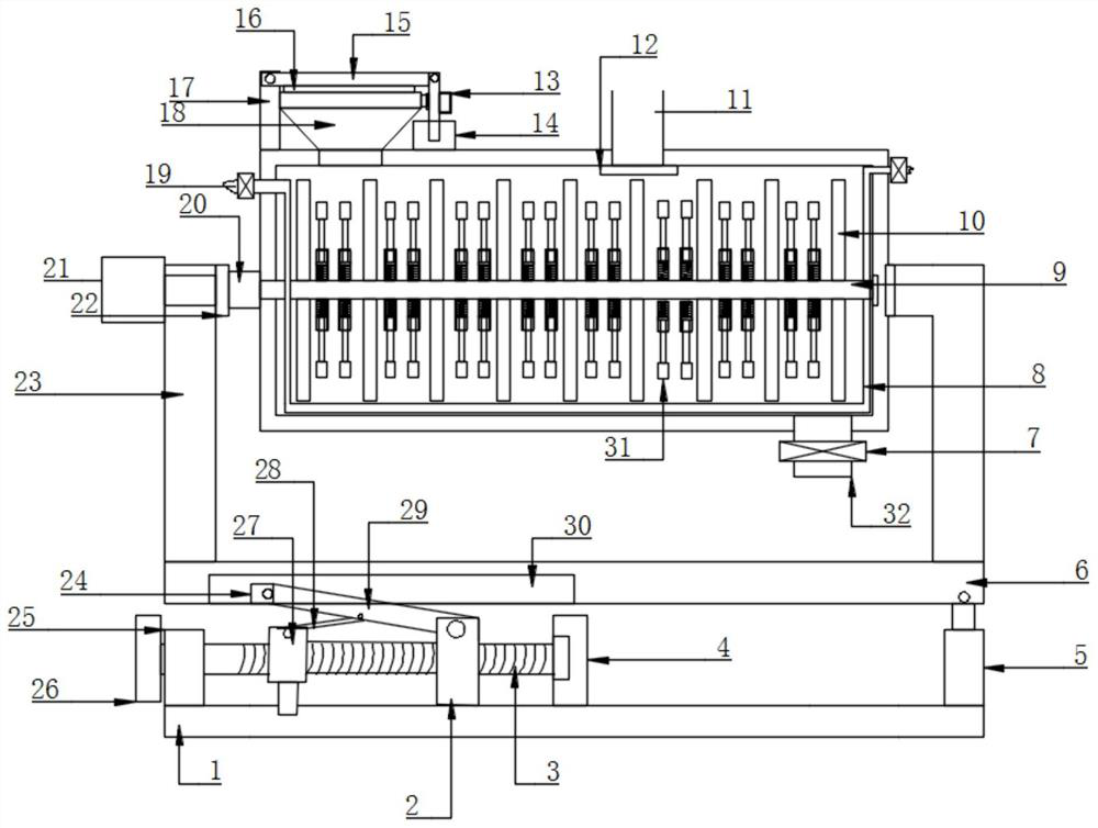
[0020] see Figure 1-4 , a thermal desorption restoration device for soil restoration, comprising a support base 1, a fixed base 6 and a thermal desorption box, the support base 1 is provided with a fixed base 6 through a blanking structure, and the fixed base 6 is provided with There is a thermal desorption box, and a thermal desorption structure is arranged inside the thermal desorption box, and the thermal desorption structure includes an inlet 18, a feeding port 32, an internal stirring structure, an inlet sealing structure, and an outlet control panel 7 , a filter screen 12 and a gas outlet pipeline 11, the inside of the thermal desorption box is rotated to be provided with an internal stirring structure, the thermal desorption box is fixed with an inlet 18, and the inlet 18 is provided with an inlet sealing structure , the bottom of the thermal desorption box is provided with a discharge port 32, the discharge port 32 is provided with an outlet control panel 7, the side ...

Embodiment 2

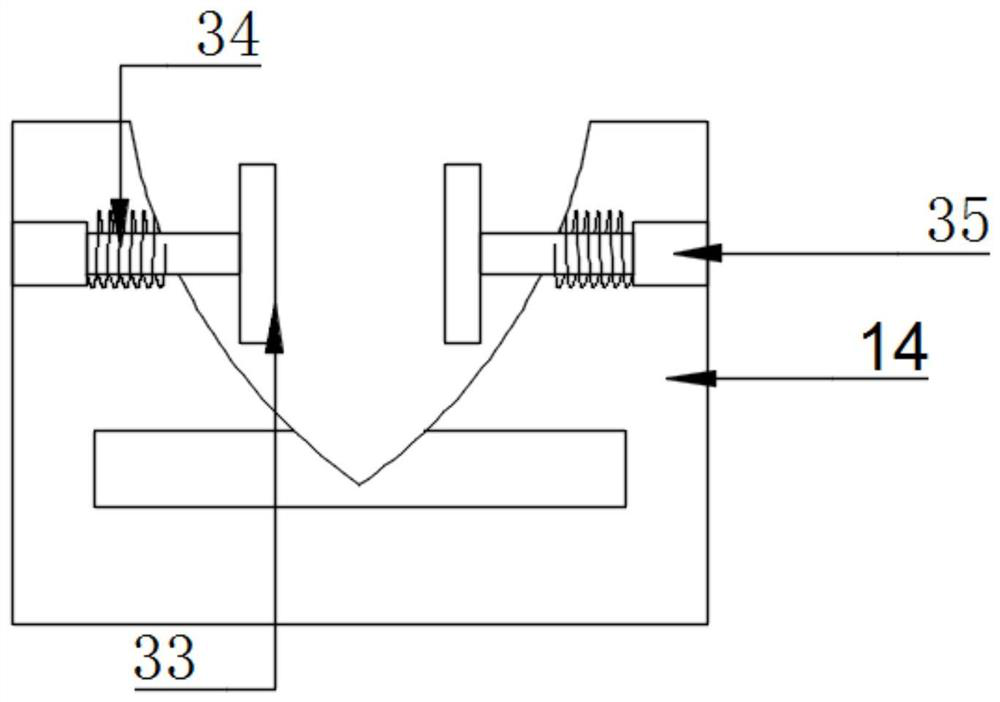
[0027] Compared with Embodiment 1, the improvement of this embodiment is that: a bottom receiving seat 14 is arranged above the thermal desorption box, and a telescopic rod 35 is arranged inside the bottom receiving seat 14, and the end of the telescopic rod 35 A clamping plate 33 is provided, and a clamping spring 34 is provided on the telescopic rod 35 . When the rotating rod rotates to the middle position of the bottom receiving seat 14, first squeeze the clamping plate 33, so that the clamping spring 34 on the telescopic rod 35 is reversely elongated, so that the clamping plate 33 has a clamping force, and the clamping spring 34 is arranged on a fixed position of the output end of the telescopic rod 35, and the other end of the clamping spring 34 is arranged at the inner fixed position of the top receiving seat 14.

[0028] The working principle of the present invention is: at first the soil to be processed enters the inside of the thermal desorption box from the inlet 18,...


PUM


Abstract

The invention discloses a thermal desorption remediation device for soil remediation. The thermal desorption remediation device for soil remediation comprises a supporting base, a fixed base and a thermal desorption box body, wherein a thermal desorption structure is arranged in the thermal desorption box body, and the thermal desorption structure comprises an inlet, a discharging opening, an internal stirring structure, an inlet sealing structure, an outlet control plate, a filter screen and a gas outlet pipeline; and a box body rotating structure comprises a side supporting rod, a rotating motor, a rotating plate and an end bearing seat. According to the invention, the thermal desorption box body capable of rotating and an internal stirring structure are arranged, so the rotating direction of the thermal desorption box body is opposite to the rotating direction of the internal stirring structure, the speed that soil absorbs heat, dissipates and vaporizes impurities during thermal desorption is increased, and thermal desorption efficiency is improved; and meanwhile, a discharging structure is arranged on the device, so the soil is prevented from being gathered in the thermal desorption box body.

Description

technical field [0001] The invention relates to a soil restoration device, in particular to a thermal desorption restoration device for soil restoration. Background technique [0002] Soil remediation is a technical measure to restore contaminated soil to normal functions, and thermal desorption remediation technology heats the soil contaminated by organic matter to above the boiling point of the organic matter, so that the organic matter in the adsorbed soil volatilizes into a gaseous state and then separates it for treatment . However, in the process of thermal desorption, because the soil gathers together, the soil receives heat unevenly, which limits the effect of thermal desorption. Contents of the invention [0003] The object of the present invention is to provide a thermal desorption remediation device for soil remediation to solve the problems raised in the above-mentioned background technology. [0004] To achieve the above object, the present invention provide...

Claims


Application Information

Patent Timeline
Patent Type & Authority Applications(China)
IPC IPC(8): B09C1/06
CPCB09C1/065
Inventor 郭文静
Owner 郭文静
Why Eureka
Try Eureka