
Mortise and tenon joint structure facilitating splicing and inserting of welded steel plates

A technology for welding steel plates and tenon and tenon joints. It is applied to the edge of workpieces, metal processing equipment, and manufacturing tools. It can solve problems such as deformation of the bed, reduce the risk of mechanical jamming, reduce work effort, and reduce stress and deformation. Effect

Pending Publication Date: 2021-06-01
山东标度智能装备有限公司
View PDF0 Cites 1 Cited by
  • Summary
  • Abstract
  • Description
  • Claims
  • Application Information

AI Technical Summary

Problems solved by technology

[0004] Aiming at the deficiencies of the existing technology, the present invention provides a mortise and tenon structure that is convenient for welding steel plates, has the advantages of avoiding welding deformation, and solves the problem that the bed is prone to deformation during welding

Method used


Image

  • Mortise and tenon joint structure facilitating splicing and inserting of welded steel plates
  • Mortise and tenon joint structure facilitating splicing and inserting of welded steel plates
  • Mortise and tenon joint structure facilitating splicing and inserting of welded steel plates

Examples


Embodiment Construction

[0027] The following will clearly and completely describe the technical solutions in the embodiments of the present invention with reference to the accompanying drawings in the embodiments of the present invention. Obviously, the described embodiments are only some, not all, embodiments of the present invention. Based on the embodiments of the present invention, all other embodiments obtained by persons of ordinary skill in the art without making creative efforts belong to the protection scope of the present invention.

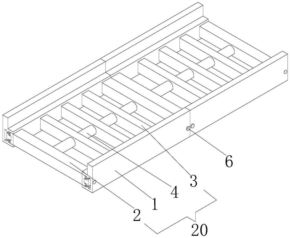
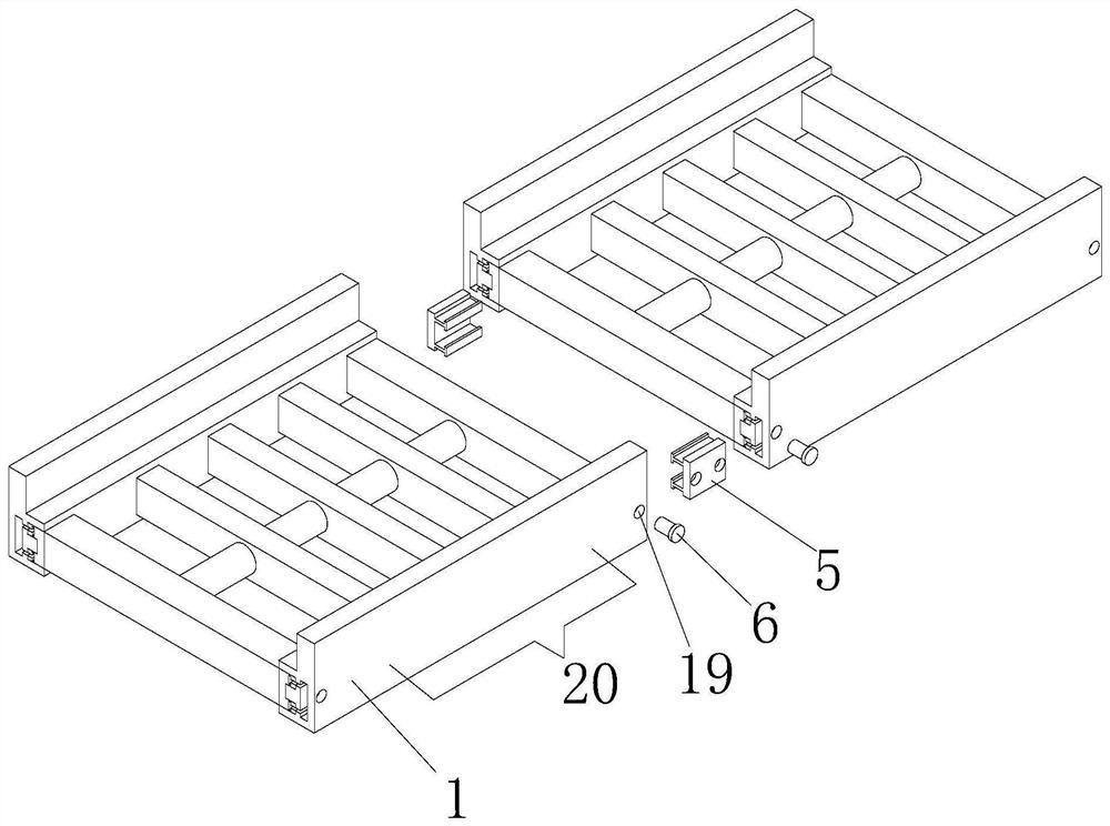
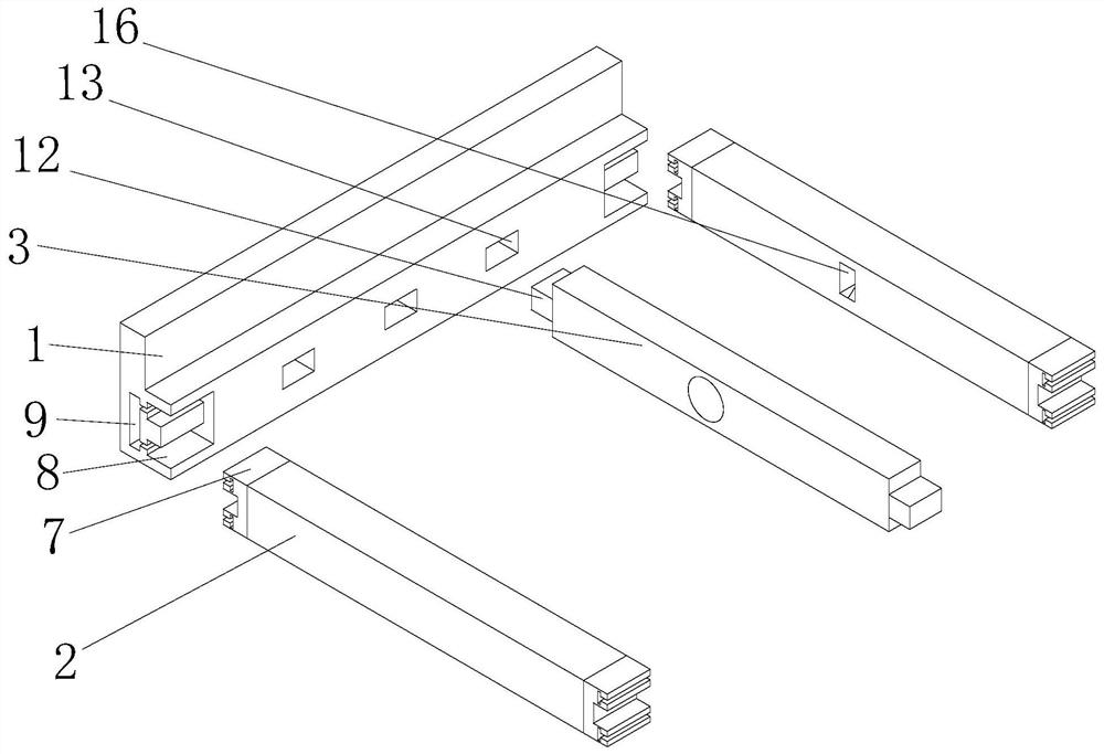
[0028] see Figure 1-Figure 6 , the present invention provides a new technical solution: a mortise and tenon structure that is convenient for welding steel plates, including a bed body 20, and the bed body 20 includes a support base plate 1, a butt plate 2, a connecting plate 3 and a connecting rod 4, The number of supporting base plates 1 is two, and the two supporting base plates 1 are set in a left and right parallel form. The docking plates 2 are respecti...


PUM


Abstract

The invention relates to the technical field of auxiliary equipment of laser cutting machines, and discloses a mortise and tenon joint structure facilitating splicing and inserting of welded steel plates. The mortise and tenon joint structure comprises a lathe bed body, and the lathe bed body comprises supporting bottom plates, butt joint plates, connecting plates and connecting rods. The butt joint plates are correspondingly arranged on the front side and the rear side between the two supporting bottom plates, the connecting plates are arranged between the two supporting bottom plates, connecting grooves are correspondingly formed in the connecting plates, the connecting grooves of the connecting plates movably sleeve the connecting rods, mortise and tenon joint mechanisms are arranged on the butt joint plates, and a splicing mechanism is arranged between the lathe bed body. According to the mortise and tenon joint structure facilitating splicing and inserting of the welded steel plates, when the lathe bed body is welded and fixed, only the positions where pins are installed need to be welded, in this way, the lathe bed body can be fixed, the working intensity of workers during welding is reduced, stress deformation during welding is reduced, the strength of the lathe bed body is improved, and then the stability of the lathe bed body is improved.

Description

technical field [0001] The invention relates to the technical field of laser cutting machine auxiliary equipment, in particular to a mortise and tenon structure that is convenient for welding steel plates. Background technique [0002] At present, China's laser cutting machine industry is developing rapidly, and there are many related industry manufacturers. Enterprises purchase more laser equipment to expand production scale. Laser cutting machines need to be laid on the installation point before the layout. It is welded through pipes or plates, and then the plates or pipes are directly assembled and welded on site according to the drawings. All joints need to be welded and must be fully welded, which results in a large amount of welding, easy deformation during welding, and difficulty in eliminating stress after welding. No welding The benchmark requires manual on-site measurement and alignment, which is easy to cause errors and low efficiency. Contents of the invention ...

Claims


Application Information

Patent Timeline
Patent Type & Authority Applications(China)
IPC IPC(8): B23K33/00
CPCB23K33/00
Inventor 苏宝剑
Owner 山东标度智能装备有限公司
Learn More