
An automatic feeding device for CNC machine tools

A technology of automatic feeding and CNC machine tools, which is applied in the field of CNC machine tools, can solve problems such as low speed and CNC machine tools do not have the function of blanking, and achieve the effect of increasing the feeding speed and working speed

Active Publication Date: 2022-04-12
唐山航翼自动化设备有限公司
View PDF0 Cites 0 Cited by
  • Summary
  • Abstract
  • Description
  • Claims
  • Application Information

AI Technical Summary

Problems solved by technology

[0003] At present, when CNC machine tools are processing various workpieces, some still need to manually place the workpieces on the machine tool for processing. When processing small rod-type or cylindrical workpieces, such as shaft rollers, cylinders, etc. etc. The CNC machine tool itself does not have a good blanking function, and the speed will become lower during the processing. Therefore, it is urgent to set up an automatic feeding device for the CNC machine tool to solve such problems

Method used


Image

  • An automatic feeding device for CNC machine tools
  • An automatic feeding device for CNC machine tools
  • An automatic feeding device for CNC machine tools

Examples


Embodiment 1

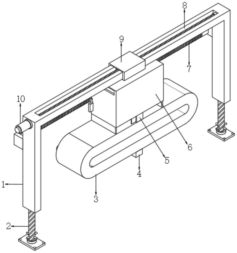
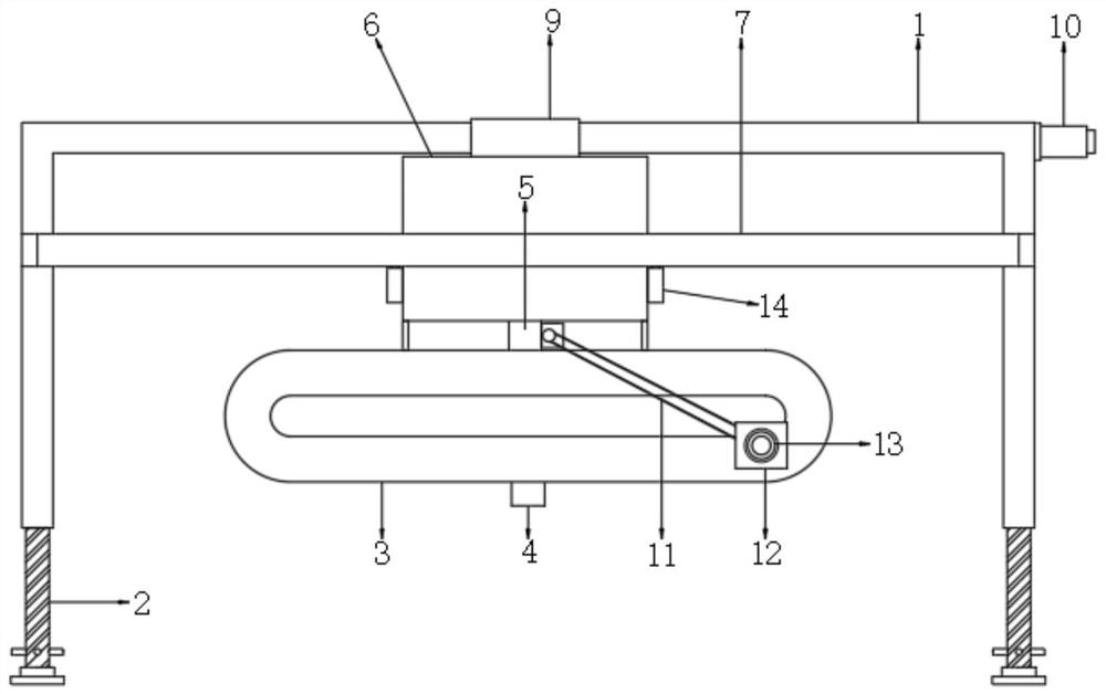
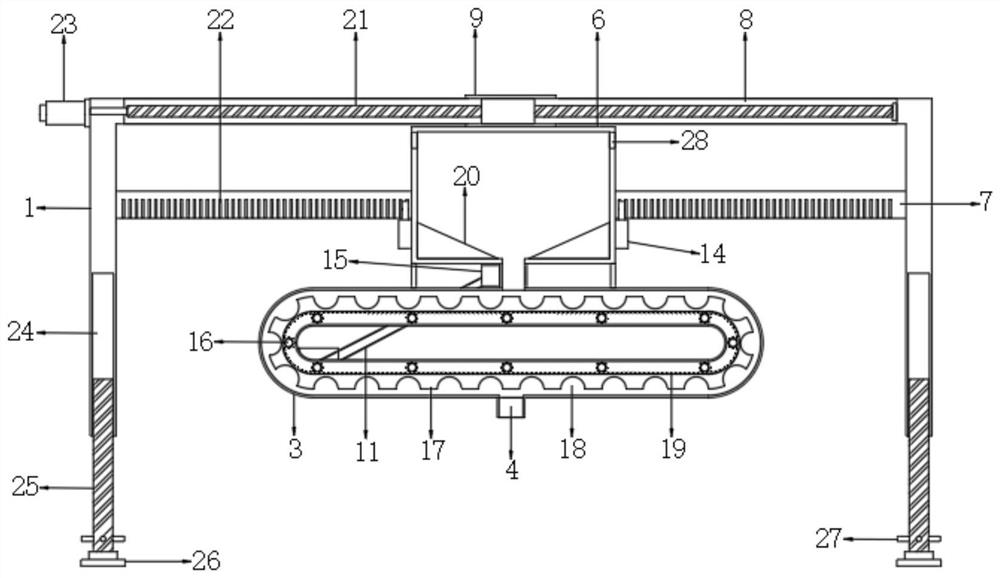
[0032] An automatic feeding device for CNC machine tools, such as Figure 1-5As shown, the support frame 1 is included, the top of the support frame 1 is provided with a transverse groove 8, and the inside of the transverse groove 8 is provided with an X-direction displacement mechanism 10, and the X-direction displacement mechanism 10 includes a threaded screw 21, and the two ends of the threaded screw 21 The end and the two ends of the transverse groove 8 are connected by bearings, and the top of one side of the outer wall of the support frame 1 is connected with a forward and reverse motor 23 by bolts, and the output shaft of the forward and reverse motor 23 and one end of the threaded screw 21 pass through Bolt connection, the outer wall of the threaded screw 21 is threadedly connected with a sliding seat, and the top and bottom of the sliding seat are connected with a movable frame 9 sleeved on the periphery of the support frame 1 through bolts, and the bottom of the movab...

Embodiment 2

[0042] An automatic feeding device for CNC machine tools, such as Figure 6 As shown, in order to solve the problem that the metal waste in the welding process is absorbed by the iron block 27; this embodiment makes the following improvements on the basis of embodiment 1: the inner walls on both sides of the storage box 6 near the bottom of the feed port 28 pass through An elastic cloth 33 is connected by bolts, and the elastic cloth 33 is arranged in a multi-layer structure, and a spring bar 34 is connected between both ends of the opposite side of the elastic cloth 33 by bolts.

[0043] In this embodiment, when a rod-type or cylindrical small-sized workpiece is dropped into the material storage box 6 through the feed port 28, the small-sized workpiece that can be made slides gradually to the inside of the material storage box 6 along the top surface of the elastic cloth 33. , in this process, due to the gravity of the workpiece, the elastic cloth 33 presents a stretching and...


PUM


Abstract

The invention discloses an automatic feeding device for a numerically controlled machine tool, which includes a support frame, a horizontal groove is opened on the top of the support frame, and an X-direction displacement mechanism is arranged inside the horizontal groove, and the X-direction displacement mechanism includes a screw thread Lead screw, the two ends of the threaded screw and the two ends of the transverse groove are connected by bearings, the top of the outer wall of one side of the support frame is fixedly connected with the forward and reverse motor, the output shaft of the forward and reverse motor is connected with one end of the threaded screw The outer wall of the threaded lead screw is screwed with a slide seat, and the top and bottom of the slide seat are fixedly connected with a movable frame sleeved on the periphery of the support frame. In the present invention, it is convenient to carry out automatic feeding processing on the CNC machine tool continuously, and the scraping bar is driven to perform instantaneous needle rotation inside the feeding pipe, and the semi-crescent scraping bar can be used to form a viscous flow process on the small workpiece, so that the workpiece It can quickly fall into the storage tank to increase the feeding speed.

Description

technical field [0001] The present invention relates to the technical field of numerical control machine tools, in particular to an automatic feeding device for numerical control machine tools. Background technique [0002] A CNC machine tool is an automated machine tool equipped with a program control system. The control system can logically process programs with control codes or other symbolic instructions, decode them, express them in coded numbers, and input them into the numerical control device through the information carrier. After calculation and processing, various control signals are sent by the numerical control device to control the movement of the machine tool, and the parts are automatically processed according to the shape and size required by the drawing. CNC machine tools solve complex, precise, small-batch, and multi-variety parts processing problems. It is a flexible, high-efficiency automatic machine tool that represents the development direction of mode...

Claims


Application Information

Patent Timeline
Patent Type & Authority Patents(China)
IPC IPC(8): B23Q7/00
CPCB23Q7/00
Inventor 黄丙军
Owner 唐山航翼自动化设备有限公司
Learn More