
Eureka
For R&D, Eureka makes reading and utilizing patents & technical documents easy.
Eureka AIR
Designed for self-driven R&D workflows. Generate viable solutions, solve complex R&D challenges, empower your innovation with AI.

Eureka Materials
Designed for material experts only. Revolutionize your material R&D, from search, analyze, to developing new materials.

TechResearch
Generate reliable direction feasibility study reports for your R&D in just a few steps.

TechSeek
Discover and master advanced knowledge NOW. Basics, ideas, possibilities, all at once.

TechMind
As an expert in R&D Theories, TechMind can generates customized viable solutions instantly.

TechRisk
Analyze your overall solution with one click, know your potential R&D risks in advance.

TechMonitor
Get weekly tech updates, stay abreast of the latest tech innovations and key insights.
Power equipment protection device
A technology for protection devices and power equipment, applied in the direction of electromechanical devices, substation/power distribution device shells, electrical components, etc., can solve the problems of poor protection effect, inconvenient use, and low flexibility, and achieve convenient operation, high flexibility, The effect of simple device structure
- Summary
- Abstract
- Description
- Claims
- Application Information
AI Technical Summary
Problems solved by technology
Method used
Image

Examples
Embodiment 1
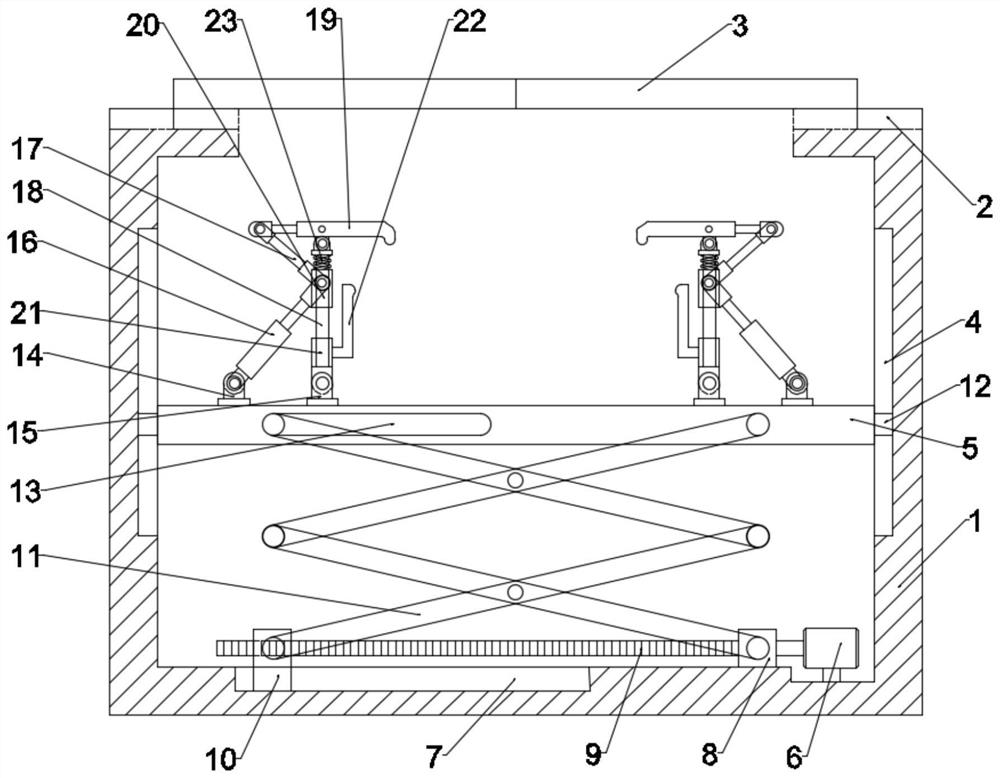
[0024] see Figure 1-2 , in an embodiment of the present invention, a power equipment protection device includes a box body 1, and a height adjustment device is provided inside the box body 1, and the height adjustment device includes a first motor 6, and the first motor 6 is detachable Connected to the box body 1, the bottom of the box body 1 is provided with a fixed seat 8, the fixed seat 8 is fixedly connected to the box body 1, and the bottom wall of the box body 1 is provided with a third chute 7. A first slider 10 is provided inside the third chute 7, and the first slider 10 is slidingly connected to the third chute 7, and the first slider 10 is connected to the fixing seat 8 is provided with a positioning bolt 9, which is rotationally connected with the fixed seat 8, and is threadedly connected between the positioning bolt 9 and the first slider 10, and the positioning The bolt 9 is detachably connected to the output shaft of the first motor 6; a telescopic rod mechani...
Embodiment 2
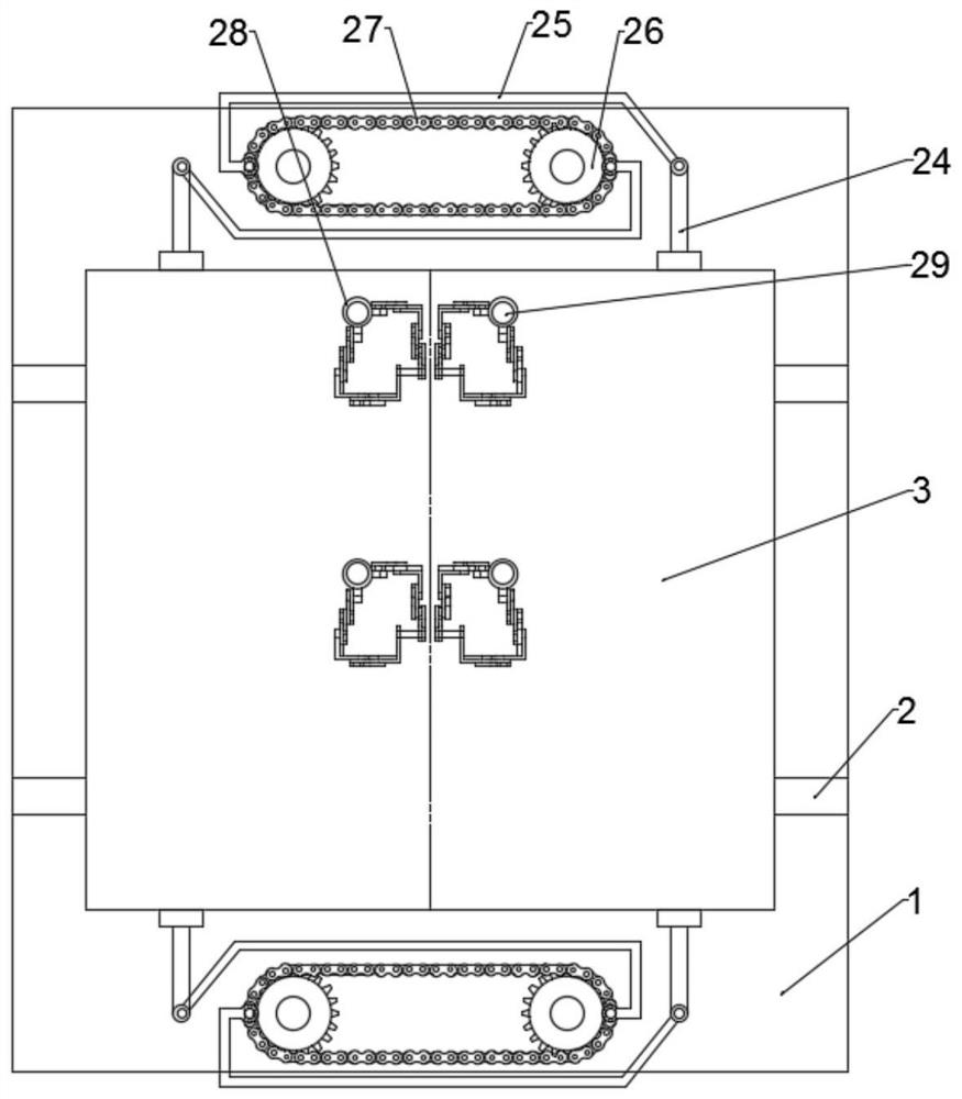
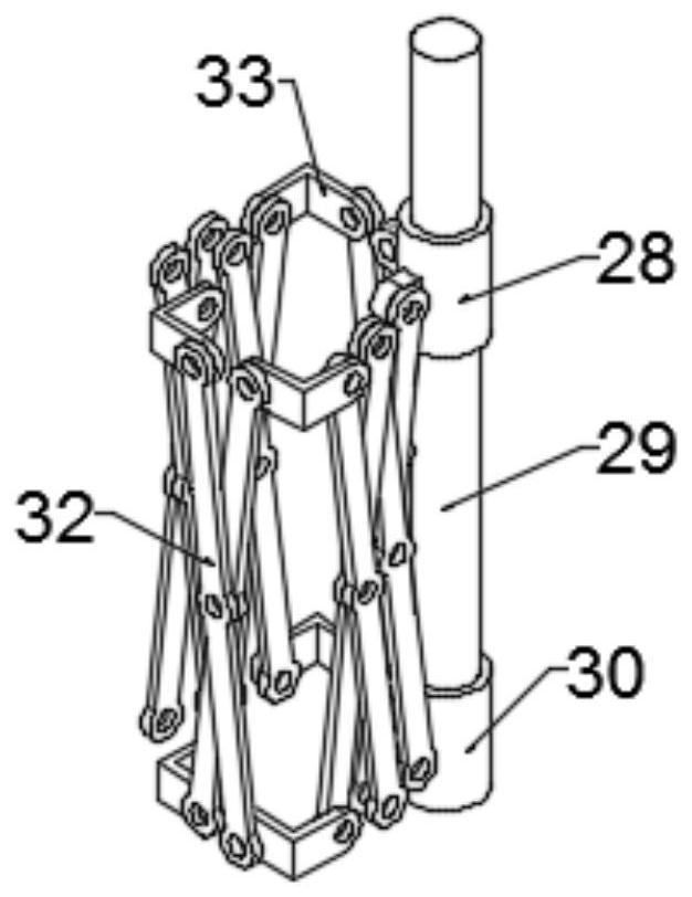
[0030] see Figure 1-5 , different from Embodiment 1, in the embodiment of the present invention, a sunshade device is provided above the sealing door 3, and the sunshading device includes a limit shaft 29, and the limit shaft 29 is detachably connected to the seal door 3 Above, the limit shaft 29 is provided with a third sliding cylinder 28 and a fixed cylinder 30, the fixed cylinder 30 is fixedly connected to the bottom of the limit shaft 29 of the box body 1, and the third sliding cylinder 28 is provided with The first pin hole 2801, the second pin hole 2901 is opened on the limit shaft 29, the first pin hole 2801 and the second pin are matched between the third sliding cylinder 28 and the limit shaft 29 through a pin shaft Hole 2901 realizes detachable connection;
[0031] Further, the third sliding cylinder 28 is provided with an ear plate 31, the fixed cylinder 30 is provided with an ear plate 31, the ear plate 31 is provided with a second telescopic rod 32, and the sec...
PUM
 Abstract
Description
Claims
Application Information
 - R&D Engineer
- R&D Manager
- IP Professional
- Industry Leading Data Capabilities
- Powerful AI technology
- Patent DNA Extraction
Browse by: Latest US Patents, China's latest patents, Technical Efficacy Thesaurus, Application Domain, Technology Topic, Popular Technical Reports.
© 2024 PatSnap. All rights reserved.Legal|Privacy policy|Modern Slavery Act Transparency Statement|Sitemap|About US| Contact US: help@patsnap.com