Soil screening equipment for soil remediation

A technology for soil screening and soil remediation, applied in the field of soil remediation, can solve the problems of high screening pressure and unsatisfactory screening effect.

Inactive Publication Date: 2021-06-04
李海慧
View PDF8 Cites 6 Cited by
  • Summary
  • Abstract
  • Description
  • Claims
  • Application Information

AI Technical Summary

Problems solved by technology

[0003] Most of the current soil remediation is through machine screening, but the vibration of the current soil remediation equipment screen generally only vibrates in one direction. At the same time, when screening, a large amount of soil will be directly put on the screen, and the screening pressure of the screen is relatively high. , the screening effect is not satisfactory

Method used


Image

  • Soil screening equipment for soil remediation
  • Soil screening equipment for soil remediation
  • Soil screening equipment for soil remediation

Examples


Embodiment 1

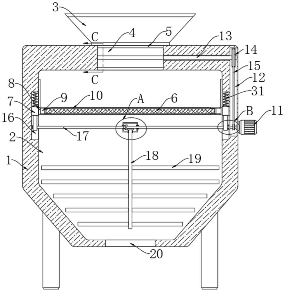
[0025] refer to Figure 1-4 , a soil screening equipment for soil remediation, comprising a shell 1, a treatment chamber 2 is arranged in the shell 1, a discharge port 20 is arranged at the inner bottom of the treatment chamber 2, and a feed port is arranged at the inner top of the treatment chamber 2 , a feeding hopper 3 is installed on the upper end of the shell 1, and the feeding hopper 3 is communicated with the upper end of the feeding port, and a cylindrical cavity 5 is arranged in the shell 1, and the cylindrical cavity 5 is located above the processing chamber 2;

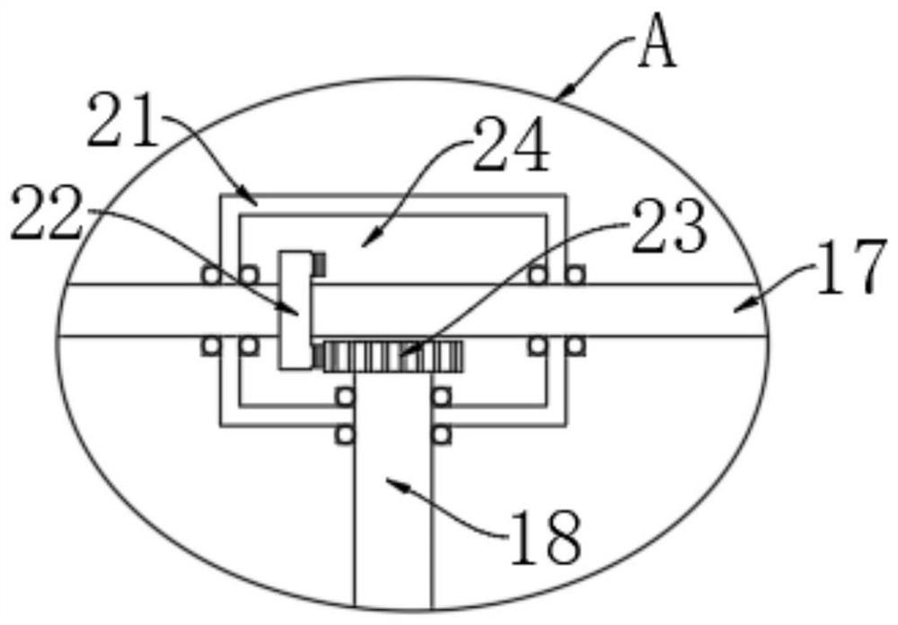
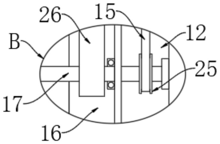
[0026] Vibration screening mechanism. The vibration screening mechanism includes a drive motor 11 installed on the right side of the housing 1. The end of the output shaft of the drive motor 11 extends into the processing chamber 2, and is fixedly connected with a first rotating rod 17. Both sides of the processing chamber 2 The inner wall is provided with a chute 16, and the two chute 16 are provided with a...

Embodiment 2

[0034] refer to Figure 5-7 , the difference between this embodiment and Embodiment 1 is that the two sides of the screen plate 6 are fixedly connected with sliding plates 27, the two sliding plates 27 are respectively located in the two installation slots 9, and the sliding plate 27 located on the left The left side of the processing chamber 2 is elastically connected to the left inner wall of the corresponding installation slot 9 through the second connecting spring 30. A sliding rod 28 is vertically arranged in the processing chamber 2. A plurality of magnetic blocks 29 are embedded in sequence, the sliding plate 27 located on the right side has magnetism, and the adjacent surfaces of the sliding plate 27 and the plurality of magnetic blocks 29 are identical and repel.

[0035] In this embodiment, when the connecting bar 8 moves up and down, the magnetic sliding plate 27 on the right side is intermittently close to the plurality of magnetic blocks 29 . The right sliding pl...


PUM


Abstract

The inventio discloses soil screening equipment for soil remediation, and the equipment comprises: a shell, in which a treatment chamber is arranged, wherein a discharging opening is formed in the inner bottom of the treatment chamber, a feeding opening is formed in the inner top of the treatment chamber, a feeding hopper is installed at the upper end of the shell and is communicated with the upper end of the feeding opening, a columnar cavity is formed in the shell, and the columnar cavity is positioned above the treatment chamber; and a vibration screening mechanism, which comprises a driving motor installed on the right side of the shell, wherein the tail end of an output shaft of the driving motor extends into the treatment chamber and is fixedly connected with a first rotating rod, and sliding grooves are formed in the inner walls of the two sides of the treatment chamber. When the screening equipment is used, only one motor is needed for driving, in the soil screening process, vertical vibration and transverse vibration can be conducted at the same time, an intermittent feeding structure is arranged, and the screening pressure of a screen can be reduced.

Description

technical field [0001] The invention relates to the field of soil remediation, in particular to soil screening equipment for soil remediation. Background technique [0002] Soil remediation is a technical measure to restore polluted soil to normal functions. In the soil remediation industry, there are more than 100 soil remediation technologies, and there are more than 10 commonly used technologies, which can be roughly divided into three types: physical, chemical and biological. method, soil screening is one of the links in soil remediation technology; [0003] Most of the current soil remediation is through machine screening, but the current soil remediation equipment screen vibration is generally only one-way vibration. At the same time, during screening, a large amount of soil will be directly put on the screen, and the screening pressure of the screen is relatively large. , the screening effect is not satisfactory. SUMMARY OF THE INVENTION [0004] The purpose of th...

Claims


Application Information

Patent Timeline
Patent Type & Authority Applications(China)
IPC IPC(8): B09C1/00B07B1/28B07B1/42B07B1/46
CPCB09C1/00B07B1/28B07B1/42B07B1/46
Inventor 李海慧
Owner 李海慧
Why Eureka
Try Eureka