Automatic distance-adjusting labeler guardrail punching and bending machining and production equipment

A technology for production equipment and labeling machines, applied in metal processing equipment, shearing machine equipment, manufacturing tools, etc., can solve the problems of low radian accuracy, increasing product conveying distance, and inability to bend in place at one time.

Inactive Publication Date: 2021-06-04
东阳市君泽钓具有限公司
View PDF0 Cites 0 Cited by
  • Summary
  • Abstract
  • Description
  • Claims
  • Application Information

AI Technical Summary

Problems solved by technology

[0004] The object of the present invention is to provide automatic distance-adjustable labeling machine guardrail punching and bending processing production equipment to solve the problem that the labeling machine proposed in the above background technology needs to pass the item through the conveying device when labeling the surface of the object It is imported to the bottom of the labeling head, and the diversion of items needs to be completed through deflectors or guardrails. According to the placement of the site, it is necessary to increase the product delivery distance through curves for sites with small spaces during production. Therefore, it is necessary to bend the deflector or the guardrail. Usually, during the bending process, the operator puts the square tube into the fixture to lock and fix it, and then bends the copper tube by manpower pulling and pushing, so that it faces the bending The accuracy of the arc of the bend is not high, and it needs to be repeatedly confirmed that it cannot be bent in place at one time.

Method used


Image

  • Automatic distance-adjusting labeler guardrail punching and bending machining and production equipment
  • Automatic distance-adjusting labeler guardrail punching and bending machining and production equipment
  • Automatic distance-adjusting labeler guardrail punching and bending machining and production equipment

Examples


Embodiment Construction

[0027] The following will clearly and completely describe the technical solutions in the embodiments of the present invention with reference to the accompanying drawings in the embodiments of the present invention. Obviously, the described embodiments are only some, not all, embodiments of the present invention. Based on the embodiments of the present invention, all other embodiments obtained by persons of ordinary skill in the art without creative efforts fall within the protection scope of the present invention.

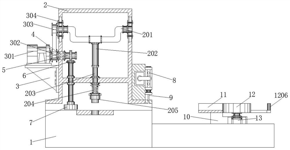
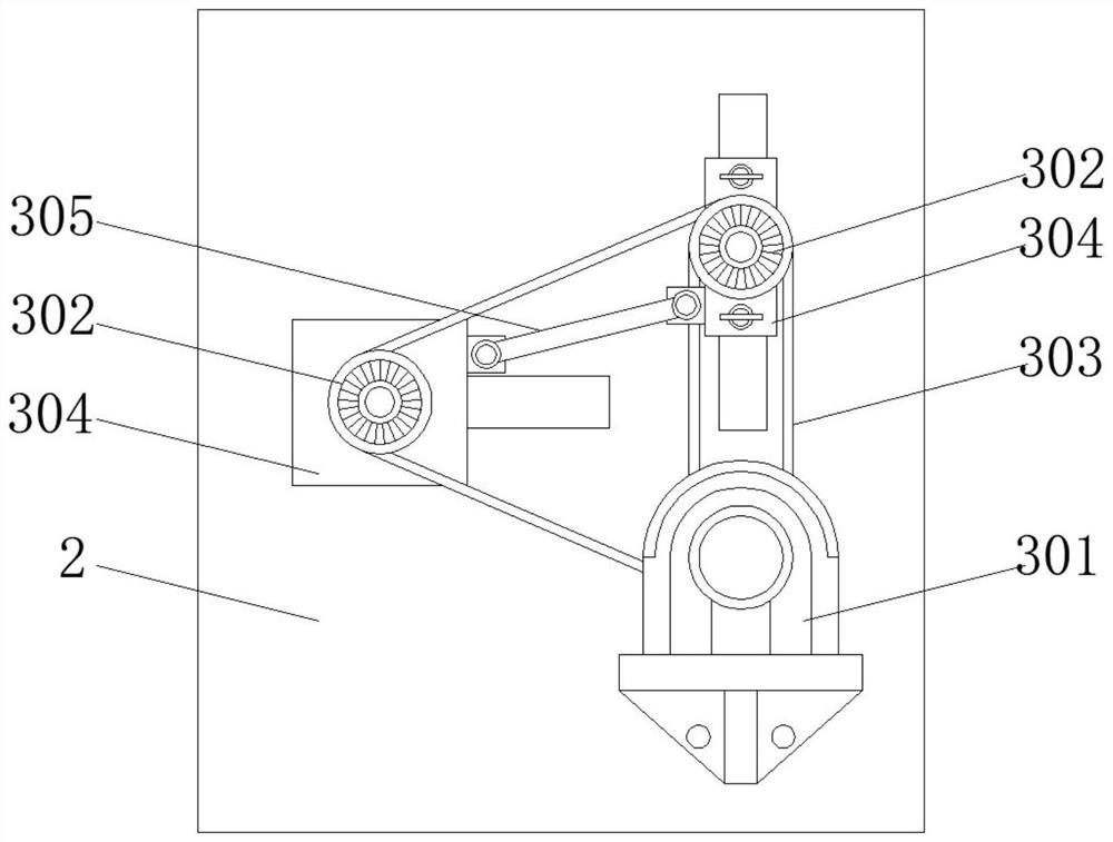
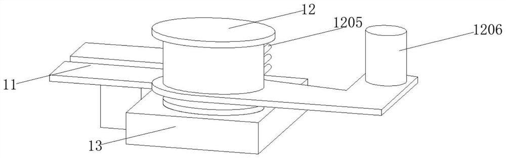
[0028] see Figure 1-5, the present invention provides a technical solution: automatic distance-adjustable labeling machine guardrail punching and bending processing production equipment, including a bottom chassis 1, a punching assembly 2 is fixedly installed on the left side of the top end surface of the bottom chassis 1, and the punching assembly The bottom of the frame of 2 communicates with the top guide groove of the bottom chassis 1, and the top of the cavit...


PUM


Abstract

The invention discloses automatic distance-adjusting labeler guardrail punching and bending machining and production equipment. The equipment comprises a bottom case, wherein a punching component is fixedly arranged at the left side of the top end face of the bottom case through a bolt; a supporting seat is arranged at the right side of the top end face of the bottom case; and a bending component is connected to the end of the right side of a flow guide frame. According to the equipment, the punching component and the bending component are arranged at the left side and the right side of the top end face of the bottom case correspondingly, a guardrail is conveniently driven to move while the guardrail is punched through the arrangement of an adjusting transmission component, meanwhile, the flow guide frame, the bending component and a flow guide groove of the bottom case are conveniently driven to be located on the same horizontal line through the arrangement of the supporting seat, and through the arrangement of a rotating motor and a first single-shaft pneumatic cylinder, after the bending component is driven to rotate, the first single-shaft pneumatic cylinder drives a cutting head to cut off the guardrail, repeated operation caused by deviation of radian data during manual turning is avoided, and therefore the radian data accuracy during bending is facilitated.

Description

technical field [0001] The invention relates to the technical field of labeling machines, in particular to punching, bending and processing production equipment for guardrails of labeling machines with automatic distance adjustment. Background technique [0002] Labeler is a device that pastes rolls of self-adhesive paper labels (paper or metal foil) on PCBs, products or prescribed packaging. The labeling machine is an indispensable part of modern packaging. It has a wide range of applications and can meet the full-circle labeling or half-circle labeling of round bottles. The labeling switch between bottles is simple and easy to adjust. The line adopts the deviation correction mechanism, the label tape does not deviate, the three directions of x / y / z and the inclination of the labeling part can be adjusted with a total of eight degrees of freedom, there is no dead angle in the adjustment, and the label overlap is high. At present, the types of labeling machines produced in my ...

Claims


Application Information

Patent Timeline
Patent Type & Authority Applications(China)
IPC IPC(8): B21D35/00B21D28/24B21D28/04B21D7/00B21D7/16B21D43/00B21D43/04B23D15/04
CPCB21D7/00B21D7/16B21D28/04B21D28/24B21D35/001B21D35/002B21D43/003B21D43/006B21D43/04B23D15/04
Inventor 王仁鑫陶一瓦
Owner 东阳市君泽钓具有限公司
Why Eureka
Try Eureka