Double-shaft-shoulder friction stir welding stirring head with four sets of auxiliary devices and method for welding curve butt welds of medium-thickness steel parts through double-shaft-shoulder friction stir welding stirring head

A technology of friction stir welding and auxiliary equipment, which is applied in the direction of welding equipment, non-electric welding equipment, process efficiency improvement, etc.

Active Publication Date: 2021-06-04
倪平涛
View PDF9 Cites 3 Cited by
  • Summary
  • Abstract
  • Description
  • Claims
  • Application Information

AI Technical Summary

Problems solved by technology

According to online inquiries, this method has not been seen at home and abroad

Method used


Image

  • Double-shaft-shoulder friction stir welding stirring head with four sets of auxiliary devices and method for welding curve butt welds of medium-thickness steel parts through double-shaft-shoulder friction stir welding stirring head
  • Double-shaft-shoulder friction stir welding stirring head with four sets of auxiliary devices and method for welding curve butt welds of medium-thickness steel parts through double-shaft-shoulder friction stir welding stirring head
  • Double-shaft-shoulder friction stir welding stirring head with four sets of auxiliary devices and method for welding curve butt welds of medium-thickness steel parts through double-shaft-shoulder friction stir welding stirring head

Examples


Embodiment Construction

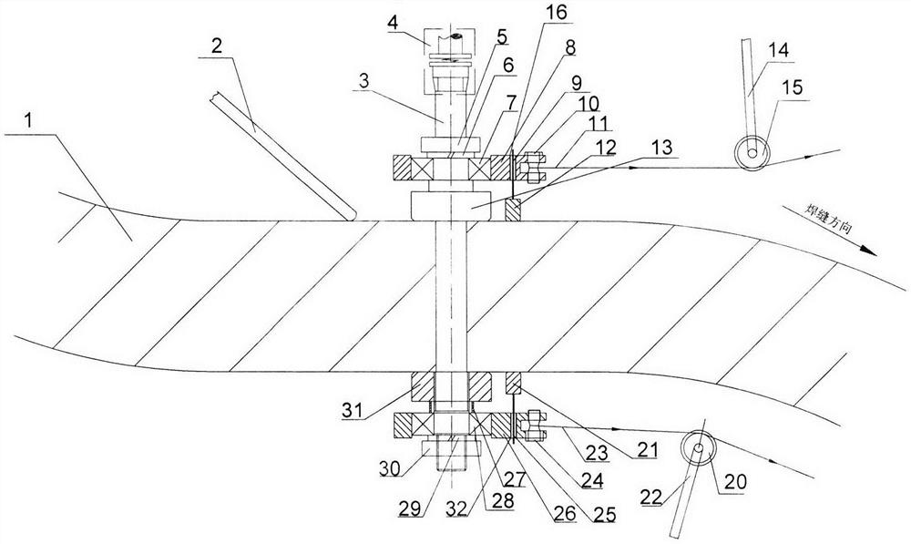
[0021] Install and fix the two parts to be welded or segmented parts that have been machined in cross-section. The height displacement should be minimized in the thickness direction of the weld and made less than 1mm or the trial value, and the gap should be eliminated by pressing in the width direction. If there are occasional or rare gaps, the value is not greater than 0.2mm or the value of the trial trial production, and the two directions should be clamped and fixed. For the assembly and welding process of devices such as stirring head and pull rope, the steps are as follows:

[0022] (1) Please refer to figure 1 , at the beginning of the stay rope 11 and the stay rope 23, pass through the fixed pulley 15 and the fixed pulley 20 respectively, according to the size of the two terminal posts 10 and 24 with a small circular arc in the middle and threads at the ends to make one for easy removal and the inserted joint sleeve (the present invention suggests equal), and carry o...


PUM


Abstract

A double-shaft-shoulder friction stir welding stirring head with four sets of auxiliary devices comprises an auxiliary pull rope, a traction device, an auxiliary current heating device, a fixed pulley, an auxiliary multi-degree-of-freedom robot with a welding seam tracking device and a flexible coupler. With the four sets of auxiliary devices, the stress condition of the stirring head can be greatly improved, the service life of the stirring head is prolonged, and the welding length of the stirring head is increased. A slope is additionally arranged on an introduction plate, so that the reduction of the pre-tightening force between the two shaft shoulders after the pre-tightening force encounters softened metal in the working process is not reduced, and tunnel type welding defects can be reduced. Notches are formed in the corners and the positions with different thicknesses, so that the double-shaft-shoulder friction stir welding stirring head is particularly suitable for friction stir welding of plane and space curve butt welds, linear butt welds and segmented part transverse butt welds of medium-thickness steel parts and steel parts which are slightly staggered in height and are equal in thickness such as various ships, various warships including aircraft carriers, conventional submarines, nuclear submarines, deep diving submersibles, large cylinders, large platforms, large flat plates and large transporters. The invention also provides a corresponding welding method.

Description

technical field [0001] The invention relates to the friction stir welding welding process of various ships, various warships including aircraft carriers, conventional submarines and nuclear submarines, deep submersibles, large cylinders, large platforms, large flat plates, and large transport aircraft. The materials can be Iron-based, nickel-based and titanium-based metals with high hardness and high melting point can also be light metals; they are especially suitable for butt welds of medium-thick or even extra-thick pieces with equal thickness and slightly dislocated planes and space curves. It is suitable for welding of thin plates and straight butt welds. Background technique [0002] Friction Stir Welding (FSW for short) is a new solid phase welding technology. Although the inventor of this patent application once proposed "a static double-shaft shoulder friction stir welding stirring head with an auxiliary rope device and a method for welding butt welds" (authorized p...

Claims


Application Information

Patent Timeline
Patent Type & Authority Applications(China)
IPC IPC(8): B23K20/12B23K20/26
CPCB23K20/122B23K20/26Y02P10/20
Inventor 倪平涛
Owner 倪平涛
Why Eureka
Try Eureka