Supercharge Your Innovation With Domain-Expert AI Agents!

Printing clamping device for non-woven fabric production

A clamping device and non-woven fabric technology, applied in the direction of printing devices, printing, printing machines, etc., can solve the problems of reduced printing efficiency, fixed printing position, and poor positional accuracy, so as to improve printing efficiency, avoid reinstallation, avoid The effect of position shifting or puckering

Active Publication Date: 2021-06-04
兰溪市睿恒新材料科技有限公司
View PDF15 Cites 3 Cited by
  • Summary
  • Abstract
  • Description
  • Claims
  • Application Information

AI Technical Summary

Problems solved by technology

[0003] However, in the printing process, the formed non-woven fabric printing requires multiple workpiece installations, which greatly reduces the printing efficiency. In the prior art, the printing process is usually carried out before the production and processing of the roll-shaped non-woven fabric. Curl winding, so as to realize the station swivel and avoid multiple installations. In the actual printing process, the offset of the printing position often leads to poor printing position accuracy, and the cutting of the processing process may easily cause damage to the printing. Different printing positions require different printing molds, and then the entire printing device needs to be replaced at the same time, which greatly reduces the printing efficiency
[0004] To this end, a printing clamping device for non-woven fabric production is provided to solve the problem of cooperation between the mold and the printing position and the problem of fixing the printing position

Method used


Image

  • Printing clamping device for non-woven fabric production
  • Printing clamping device for non-woven fabric production
  • Printing clamping device for non-woven fabric production

Examples


Embodiment Construction

[0025] The following will clearly and completely describe the technical solutions in the embodiments of the present invention with reference to the accompanying drawings in the embodiments of the present invention. Obviously, the described embodiments are only some, not all, embodiments of the present invention. Based on the embodiments of the present invention, all other embodiments obtained by persons of ordinary skill in the art without making creative efforts belong to the protection scope of the present invention.

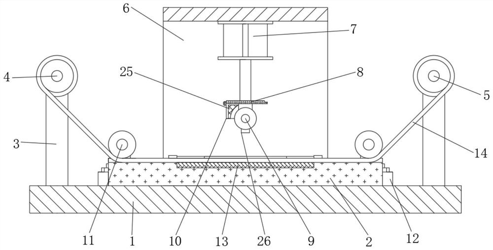
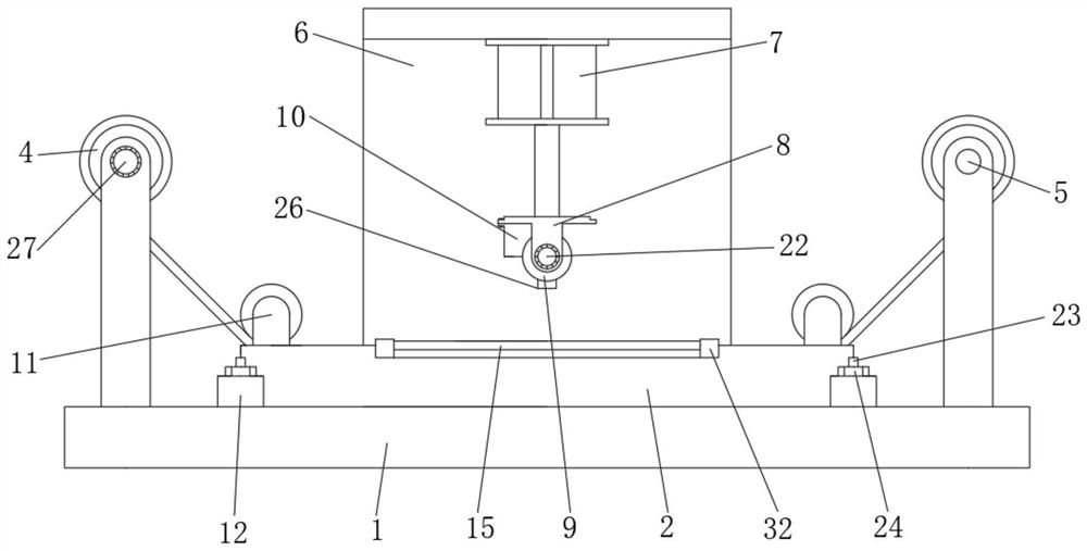
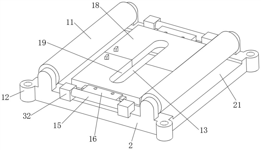
[0026] see Figure 1 to Figure 5 , the present invention provides a technical solution:

[0027] A printing clamping device for non-woven fabric production, comprising a printing workbench 1, a jig plate 2 is installed in the middle of the upper end surface of the printing workbench 1, and four jig plates distributed in a matrix are arranged on the upper end surface of the printing worktable 1. The positioning column 23 installed vertically, the four corner p...


PUM


Abstract

The invention relates to the technical field of non-woven fabric production, in particular to a printing clamping device for non-woven fabric production. The printing clamping device comprises a printing worktable, a jig plate is installed in the middle of the upper end face of the printing worktable, supports are symmetrically and vertically welded on the left side and the right side of the upper end face of the printing worktable, an inverted L-shaped side plate is vertically welded on the rear side of the printing worktable, and a hydraulic cylinder is fixedly installed at the lower end of a cross beam at the upper end of a side plate. The printing clamping device has the beneficial effects that by arranging an iron sheet pressing plate which is installed in an inserted mode, the position of a printing groove can be conveniently replaced and installed, reinstallation of equipment is avoided, the printing efficiency is improved, and meanwhile the adaptability between the printing groove and a printing mold is improved; and by arranging the jig plate and the rotationally-installed iron sheet pressing plate, position pressing and fixing of the non-woven fabric in the printing section are achieved, position deviation or wrinkles are avoided, the precision of the printing position is greatly improved, and meanwhile the stability of station conversion of the non-woven fabric is enhanced.

Description

technical field [0001] The invention relates to the technical field of non-woven fabric production, in particular to a printing clamping device for non-woven fabric production. Background technique [0002] In the production process of non-woven fabrics, the outer wall of non-woven fabrics needs to be aesthetically designed, and mold printing is usually used to enhance the appearance of non-woven fabrics. [0003] However, in the printing process, the formed non-woven fabric printing requires multiple workpiece installations, which greatly reduces the printing efficiency. In the prior art, the printing process is usually carried out before the production and processing of the roll-shaped non-woven fabric. Curl winding, so as to realize the station swivel and avoid multiple installations. In the actual printing process, the offset of the printing position often leads to poor printing position accuracy, and the cutting of the processing process may easily cause damage to the p...

Claims


Application Information

Patent Timeline
IPC IPC(8): B41F17/00
CPCB41F17/003B41F17/005B41P2217/10B41P2217/50
Inventor 王秋萍
Owner 兰溪市睿恒新材料科技有限公司
Features
  • R&D
  • Intellectual Property
  • Life Sciences
  • Materials
  • Tech Scout
  • Unparalleled Data Quality
  • Higher Quality Content
  • 60% Fewer Hallucinations
Learn More