Unmanned aerial vehicle and working method thereof

A technology for unmanned aerial vehicles and aircraft, which is applied in the aviation field and can solve the problems of motor damage, being easily entangled by foreign objects, and potential safety hazards.

Active Publication Date: 2021-06-04
福建汇仟航空科技有限公司
View PDF8 Cites 0 Cited by
  • Summary
  • Abstract
  • Description
  • Claims
  • Application Information

AI Technical Summary

Problems solved by technology

[0002] Unmanned aerial vehicle is an unmanned aerial vehicle controlled by radio remote control equipment and self-contained program control device. Compared with manned aircraft, it has small size, low cost, easy to use, low requirements for combat environment, and high battlefield survivability. Strong and other advantages; at present, unmanned aerial vehicles generally include the fuselage, the propeller that provides flight power, etc., after the existing unmanned aerial vehicle falls abnormally, the propeller is still in the rotating state, and it is easy to be entangled by foreign objects and cause damage to the motor; or when When the unmanned aerial vehicle landed far away, sometimes the unmanned aerial vehicle did not shut down in time, causing children to be injured by the propeller; in addition, the propeller of some unmanned aerial vehicles can still start to rotate after being folded, which has a greater safety hazard

Method used


Image

  • Unmanned aerial vehicle and working method thereof
  • Unmanned aerial vehicle and working method thereof
  • Unmanned aerial vehicle and working method thereof

Examples


Embodiment Construction

[0038] The present invention will be described in detail below in conjunction with the accompanying drawings and specific embodiments.

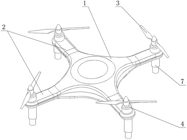
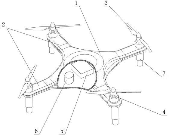
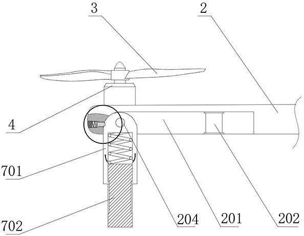
[0039] see Figures 1 to 3, an unmanned aerial vehicle, comprising a fuselage 1 of the aircraft, a plurality of arms 2 fixedly connected to the fuselage 1, a propeller 3 fixed on the upper end of the outer side of the arm 2, and the propeller 3 is provided by a motor arranged above the arm 2 4 drive to rotate; the inside of the fuselage 1 is provided with a battery 5 to drive the operation of the aircraft, and a controller 6 for controlling the operation of the aircraft; the bottom of the outer end of the support arm 2 is provided with a folding landing gear 7 hinged with the support arm 2 , the undercarriage 7 includes a hollow main cylinder 701 with a hole at one end, a telescopic rod 702 slidingly connected with the main cylinder 701, two electrodes 703 are radially symmetrically arranged on the inner wall of the main cylinder 701, and the...


PUM


Abstract

The invention relates to an unmanned aerial vehicle and a working method thereof. The unmanned aerial vehicle comprises an aerial vehicle body, a plurality of supporting arms fixedly connected with the aerial vehicle body and propellers fixed to the upper ends of the outer sides of the supporting arms. A battery for driving the aircraft to operate and a controller for controlling the aircraft to operate are arranged in the aerial vehicle body; a folding undercarriage hinged to the supporting arm is arranged below the end of the outer side of the supporting arm, the undercarriage comprises a hollow main cylinder with one end provided with a hole and a telescopic rod slidably connected with the main cylinder, two electrodes are symmetrically arranged on the inner wall of the main cylinder in the radial direction and electrically connected with the controller, and the telescopic rod is made of a conductive metal material. When the telescopic rod contracts towards the interior of the main cylinder, the two electrodes are connected and conducted through the telescopic rod; the unmanned aerial vehicle controls the on/off of the electrode through the up/down movement of the telescopic rod during landing and landing, the controller controls the propeller to rotate or stop through the electric signal introduced by the electrode, the reaction is sensitive, the safety is high, and the continuous rotation of the propeller after the unmanned aerial vehicle lands is effectively avoided.

Description

technical field [0001] The invention relates to the field of aviation, in particular to an unmanned aerial vehicle and a working method thereof. Background technique [0002] Unmanned aerial vehicle is an unmanned aerial vehicle controlled by radio remote control equipment and self-contained program control device. Compared with manned aircraft, it has small size, low cost, easy to use, low requirements for combat environment, and high battlefield survivability. Strong and other advantages; at present, unmanned aerial vehicles generally include the fuselage, the propeller that provides flight power, etc., after the existing unmanned aerial vehicle falls abnormally, the propeller is still in the rotating state, and it is easy to be entangled by foreign objects and cause damage to the motor; or when When the unmanned aerial vehicle landed far away, sometimes the unmanned aerial vehicle did not shut down in time, causing children to be injured by the propeller; in addition, the...

Claims


Application Information

Patent Timeline
Patent Type & Authority Applications(China)
IPC IPC(8): B64C39/02B64C25/12B64C25/62B64C27/14
CPCB64C39/024B64C25/12B64C25/62B64C27/14B64C2025/125B64U2201/20
Inventor 李闽生
Owner 福建汇仟航空科技有限公司
Why Eureka
Try Eureka