
Steam pipeline pressurization system and full-automatic control method thereof

A technology of pressurization system and steam pipeline, applied in pipeline system, pump control, machine/engine, etc., can solve the problems of system hazards, system damage, complex structure, etc., to reduce operating costs, avoid factory maintenance costs, and save water The effect of electrical overhead

Pending Publication Date: 2021-06-04
CHONGQING JIANGJIN SHIPBUILDING IND
View PDF11 Cites 1 Cited by
  • Summary
  • Abstract
  • Description
  • Claims
  • Application Information

AI Technical Summary

Problems solved by technology

The high-speed centrifugal steam pipeline pressurization system has the possibility of surge, which may cause great harm to the unit itself and even the entire system
In addition, among all the equipment in major smelters, paper mills, and power plants, the steam pipeline pressurization system has a more complex structure, more accessories, and more complicated operation and control procedures than other equipment. The main engine and accessories are all controlled by humans, which will inevitably bring a lot of inconvenience to the operator, and the efficiency of the system operation is also low. Even due to operational errors, it will cause great damage to the unit and the entire system. Therefore, a steam pipeline booster is invented. The fully automatic control method of the pressure system is very critical and necessary.

Method used

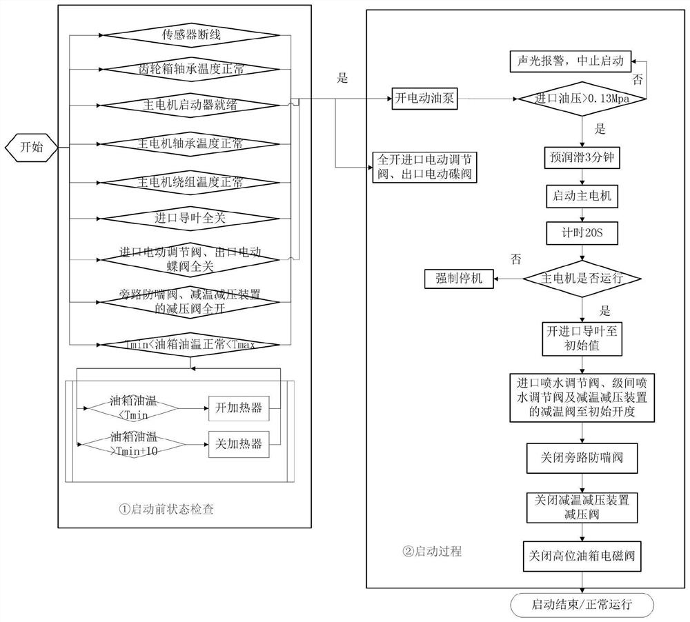
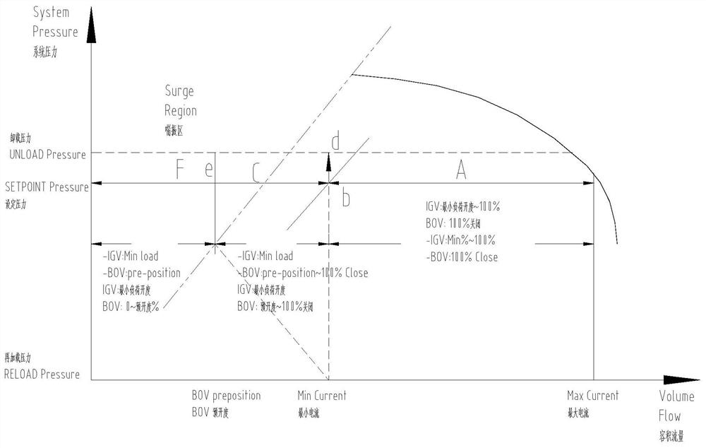
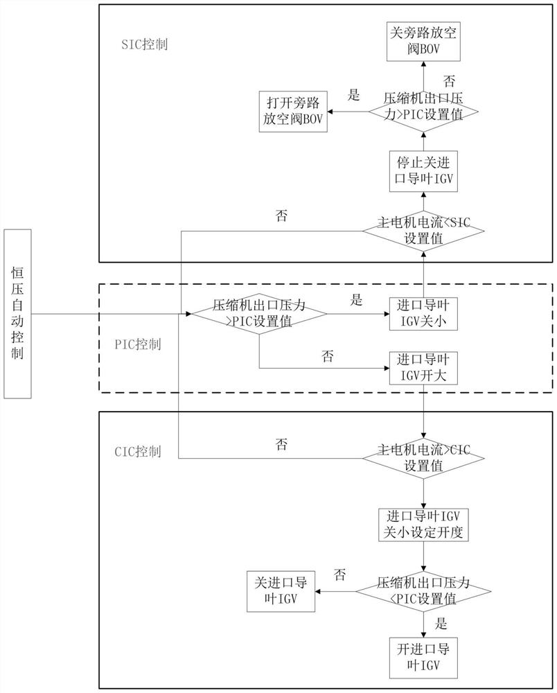

Image

  • Steam pipeline pressurization system and full-automatic control method thereof
  • Steam pipeline pressurization system and full-automatic control method thereof
  • Steam pipeline pressurization system and full-automatic control method thereof

Examples


Embodiment Construction

[0055] Below in conjunction with accompanying drawing, the present invention will be further described,

[0056] see Figure 1-Figure 8 , a steam pipeline pressurization system, including a steam inlet buffer tank 1 and an exhaust steam buffer tank 2, the steam inlet buffer tank 1 buffers the input primary low-pressure saturated steam, and the exhaust steam buffer tank 2 buffers the pressurized secondary The sub-saturated high-pressure steam is buffered, and the buffered secondary high-pressure saturated steam is incorporated into the main pipeline. The pressurization system further includes:

[0057] The inlet guide vane mechanism 3 is connected to the steam inlet buffer tank 1 through the steam inlet pipeline 4, and the steam inlet regulating valve 5 is arranged on the steam inlet pipeline 4, which is used to adjust the flow of low-pressure saturated steam entering the inlet guide vane mechanism;

[0058] The first stage 6 of the compressor is connected to the outlet end of...


PUM


Abstract

The invention discloses a steam pipeline pressurization system. The system involves a steam inlet buffer tank, a steam exhaust buffer tank, an inlet guide vane mechanism, a compressor first stage and a compressor second stage, wherein the compressor second stage and the steam exhaust buffer tank are connected through a steam exhaust pipeline, a bypass pipeline is arranged between a steam inlet pipeline and the steam exhaust pipeline, the bypass pipeline is provided with an anti-surge valve and a temperature and pressure reducing device, the temperature and pressure reducing device is internally provided with a temperature reducing valve and a pressure reducing valve, the system further involves a gear box, a main motor, a lubricating oil system, a plurality of temperature sensors, a pressure sensor and a PLC control system, a control instruction is sent to the pressurization system for full-automatic control, a full-automatic control method of the steam pipeline pressurization system is further disclosed, and the full-automatic control method comprises a starting mode, a constant-pressure self-control mode, a spraying system self-control mode, an automatic anti-surge mode, a stopping mode and a whole-process online monitoring mode. The steam pipeline pressurization system is in the six control modes, so that full-automatic control over the whole system in the whole process of starting, stopping and normal operation can be realized.

Description

technical field [0001] The invention relates to the technical field of turbocharger automatic control, in particular to a steam pipeline supercharging system and a fully automatic control method thereof. Background technique [0002] The steam pipeline pressurization system is widely used in the recovery and utilization of low-pressure waste steam in major smelters, paper mills, power plants, etc. The principle is to repressurize a large amount of low-pressure waste steam generated after heat exchange by various heat exchange equipment in the plant, and transform it into usable high-pressure steam to participate in various processes in the plant. Compared with other types of systems, the high-speed centrifugal steam pipeline pressurization system has the advantages of high efficiency, wide range of flow adjustment, oil-free medium, stable pressure, low noise, and high degree of automation, so it has been more and more widely used. The high-speed centrifugal steam pipeline p...

Claims


Application Information

Patent Timeline
Patent Type & Authority Applications(China)
IPC IPC(8): F17D1/06F17D1/07F17D3/01F17D5/00F04D27/00F04D27/02F04D29/58
CPCF17D1/06F17D1/07F17D3/01F17D5/005F04D27/00F04D27/001F04D27/002F04D27/008F04D27/0215F04D29/5846
Inventor 尹贤军谢小华文鑫但光局熊涛龚由春邓德见曾勇谭轻松孙冬婷
Owner CHONGQING JIANGJIN SHIPBUILDING IND
Learn More