A high-sensitivity bionic lateral water flow and water pressure sensing array structure

A high-sensitivity, array-structured technology, applied in the measurement of fluid pressure, fluid velocity, underwater operation equipment, etc., to achieve the effects of enhancing detection sensitivity, increasing surface area, and increasing local flow velocity

Active Publication Date: 2022-02-11
XI AN JIAOTONG UNIV
View PDF8 Cites 0 Cited by
  • Summary
  • Abstract
  • Description
  • Claims
  • Application Information

AI Technical Summary

Problems solved by technology

[0004] In view of the above problems, the object of the present invention is to imitate the lateral line sensory organ of fish, and provide a bionic lateral line water pressure sensing array with simple structure and high-precision detection capability, that is, to imitate the surface neuromast of fish and have a local shrinkage structure Design and integrate the pipeline neuromasts into an overall structure to supplement the defects of the previous single research on the surface neuromast structure or pipeline neuromast structure, high-precision sensing of water pressure changes to achieve a more comprehensive understanding of The function of target detection

Method used


Image

  • A high-sensitivity bionic lateral water flow and water pressure sensing array structure
  • A high-sensitivity bionic lateral water flow and water pressure sensing array structure
  • A high-sensitivity bionic lateral water flow and water pressure sensing array structure

Examples


Embodiment Construction

[0025] In order to fully and clearly demonstrate the purpose, technical solutions and advantages of the present invention, the present invention will be further described in detail below in conjunction with the embodiments and accompanying drawings. It should be noted in advance that the given schematic implementations and accompanying drawings are only used to explain the present invention, and are not intended to limit the present invention.

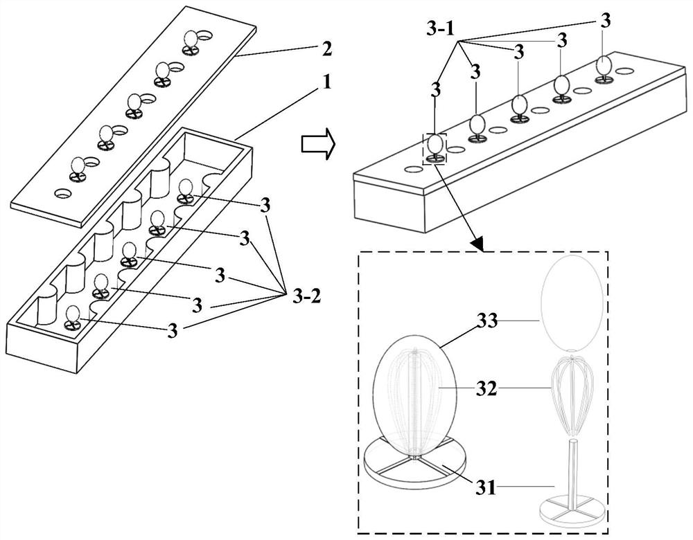
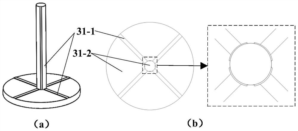
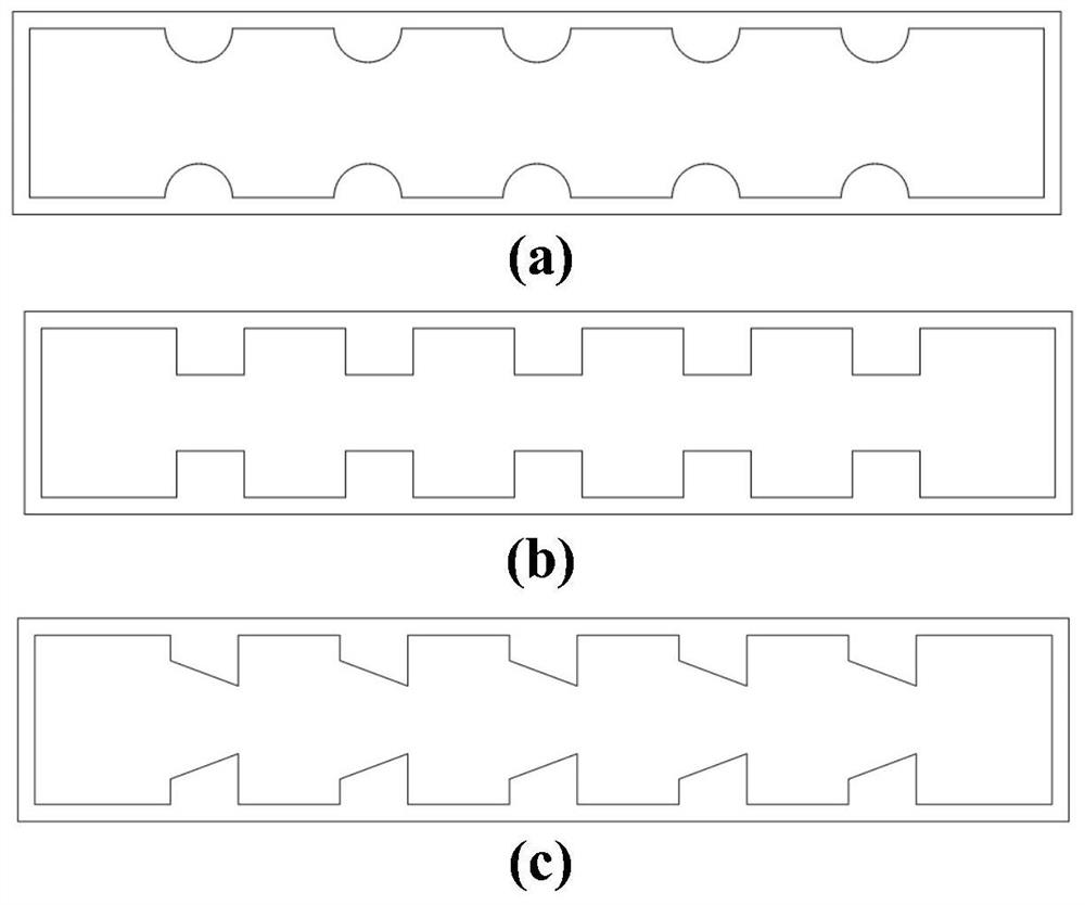
[0026] The purpose of the present invention is to imitate the lateral line sensory organ of fish, and provide a bionic side line water pressure sensing array with simple structure, easy manufacture and high precision, that is, to simultaneously imitate the local contraction structure of the lateral line duct neuromast of fish and the The bionic sensitive roof structure on the cilium structure of the lateral line can effectively improve the sensitivity and accuracy of perception, and integrate the channel neuromast and surface neuromast ...


PUM


Abstract

The invention discloses a high-sensitivity bionic lateral line water flow and water pressure sensing array structure. Part of the ciliary structure on the base body is nested in the cavity of the bracket, and the bionic sensitive top covers and connects the part of the ciliary structure on the base body and the bracket. Five bionic sensors are respectively attached to the top of the upper cover of the pipeline and in the cavity of the bionic local shrinkage pipeline, and they are distributed in an array along the length direction, correspondingly forming the bionic surface neuromast sensing array and the bionic pipeline neuromast sensing array, which are used to sense water flow respectively Variations and differential pressure gradients. The upper cover plate of the pipeline is provided with a through hole along its length direction, and the bottom of the upper cover plate of the pipeline is combined with the upper part of the bionic partial shrinkage pipeline through a waterproof sealant. It can effectively increase the local flow velocity, and the combination of the bionic sensitive top structure and the tree crown skeleton framework by using porous hydrogel materials with strong water absorption can effectively improve the interaction force between water and the sensing unit structure to enhance its sensing response signal, thereby Effectively improve its detection sensitivity and accuracy.

Description

technical field [0001] The invention belongs to the technical field of underwater sensors, in particular to a high-sensitivity bionic side-line water flow and pressure sensing array. Background technique [0002] The continuous advancement of underwater equipment technology and the complexity of its underwater environment have strengthened the need for underwater equipment to perceive the environment. Traditional underwater vehicle or underwater robot detection methods have some defects, such as sonar detection The detection method is prone to blind spots, while the camera and laser detection methods are more likely to be constrained by vision, and the perception signal is relatively single, which makes it impossible to perceive short-range disturbances, let alone judge changes in the surrounding environment. However, underwater detection Technology is also an important means of equipment required for naval warfare. [0003] After hundreds of millions of years of evolution,...

Claims


Application Information

Patent Timeline
Patent Type & Authority Patents(China)
IPC IPC(8): G01L13/00G01L19/00G01P5/00B63C11/52
CPCG01L13/00G01L19/00G01P5/00B63C11/52
Inventor 胡桥杨倩朱子才刘钰李思虎李怡昕
Owner XI AN JIAOTONG UNIV
Why Eureka
Try Eureka