
Direct tensile test instrument for annular rock sample

A technique for tensile testing and rock samples, applied in instruments, scientific instruments, sampling devices, etc., can solve the problems of large test interference, low actual value, and difficult operation, so as to achieve easy sample preparation and avoid stress concentration , The effect of simple principle

Active Publication Date: 2021-06-04
CHINA UNIV OF PETROLEUM (EAST CHINA) +1
View PDF10 Cites 0 Cited by
  • Summary
  • Abstract
  • Description
  • Claims
  • Application Information

AI Technical Summary

Problems solved by technology

[0005]Direct Tensile TestDisc Split Method TestMechanical ModelThe principle is simple and the closest to the actual valueThe model is more complex, lower than the actual valueRock sample productionHigh requirements, low success rateHigh requirements, existing standardsTest equipmentIt is difficult to operate and difficult to control accuratelySimple equipment and easy to control Influencing factors of the testThe rock sample is not easy to hold, the pulling force should coincide with the central axisThere is a premise, the material size of the pad ,Scope of applicationThe applicable object is wider, the use is less, it is not easy to be used in soft rockThe applicable object is wider, Currently more commonly used
[0006]As mentioned above, the current tensile strength test method has a large corresponding test interference due to the change of loading contact conditions, and there are test assumptions and mechanical models Many influencing factors, such as the approximate error of selection and the error in numerical calculation, make the test results of these methods show randomness and instability, and fail to form a widely recognized and referenced rock tensile strength test standard.

Method used


Image

  • Direct tensile test instrument for annular rock sample
  • Direct tensile test instrument for annular rock sample
  • Direct tensile test instrument for annular rock sample

Examples


Embodiment Construction

[0058] The implementation of the present invention will be described in detail below in conjunction with the accompanying drawings.

[0059] Step 1. Rock sample preparation

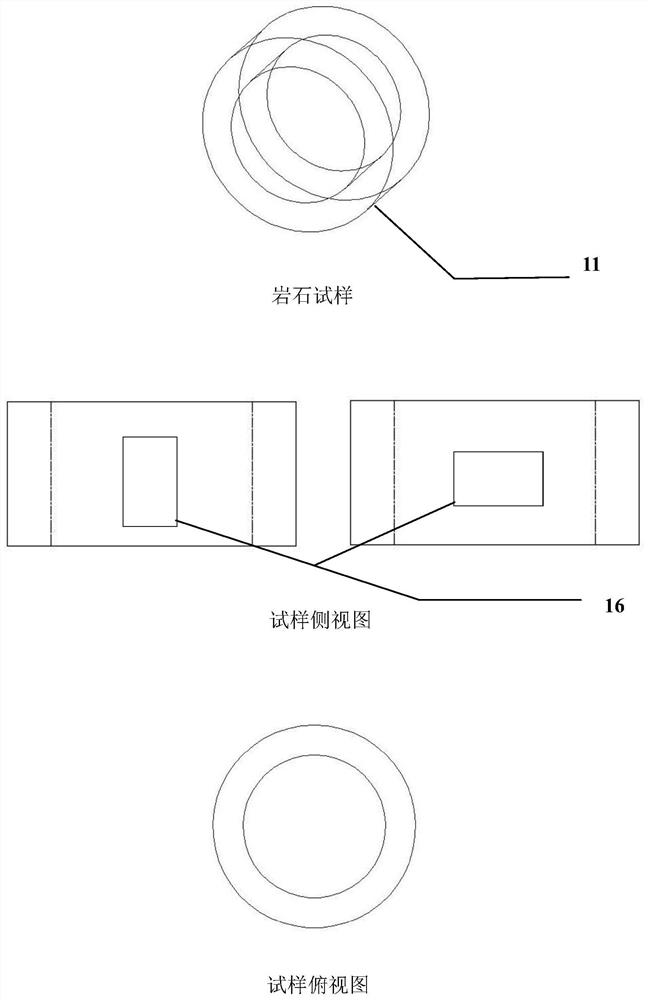
[0060] Prepare the ring sample 11, on the surface of the sample according to figure 2 A strain gauge 16 is attached as shown.

[0061] Step 2. Install the Specimen

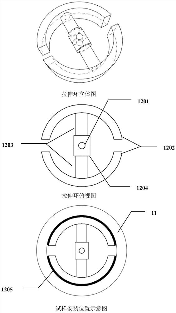
[0062] Unscrew the tension ring oil port 1201, and take off the tempered glass cover 13, such as image 3 Test specimen 11 and tension ring 12 are shown mounted in place. After the sample is installed, install the glass cover and tighten the tension ring oil port 1201.

[0063] Step 3. Exhaust the instrument line

[0064] Open the shut-off valve 1 and the air release valve 3, close the shut-off valve 4, start the hydraulic station 14, inject hydraulic oil into the pipeline, and close the hydraulic station 14, air release valve 3, Stop valve 1.

[0065] Step 4. Add liquid to the servo pump

[0066] Close the shut-off valve 4, open the...


PUM


Abstract

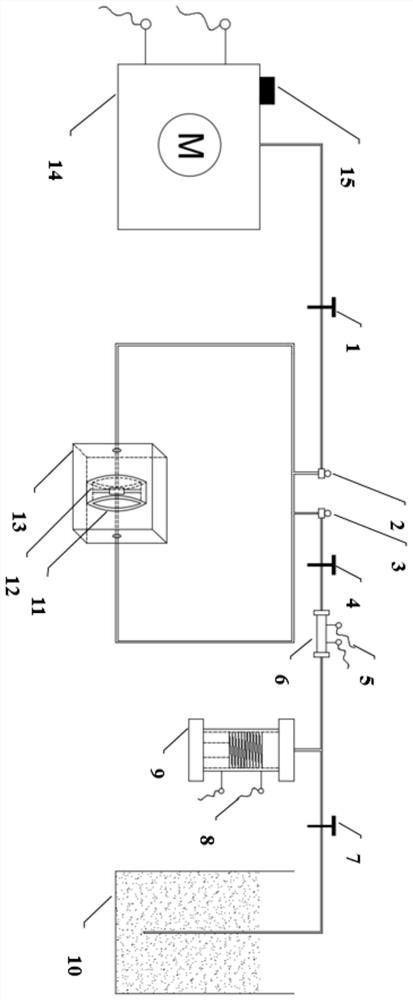
The invention discloses a direct tensile test instrument for an annular rock sample. The invention provides a direct tensile test instrument for an annular rock sample aiming at tensile failure of rocks, so that the tensile strength of the rocks and the elastic modulus E and the Poisson's ratio mu in the tensile process are obtained. The direct tensile test instrument comprises three parts, namely a loading system, a pressure monitoring and data acquisition system and sample preparation. The loading system comprises a hydraulic station, a servo pump, a stretching ring, a rubber gasket and a supplementing groove. The pressure monitoring and data acquisition system comprises a sensor and a data acquisition system. The stretching ring decoration comprises an arc-shaped pressing head, a piston rod, an oil cylinder and a rubber gasket. The rock sample is a specially prepared circular sample. The test instrument is simple in principle and easy to operate and control, the sample is easy to prepare, and the tensile strength of various rock sample sizes and the elastic modulus E and the Poisson's ratio mu in the tensile process of the rock can be accurately and effectively measured.

Description

Technical field: [0001] The invention relates to the technical field of indoor rock strength testing, in particular to an instrument for direct tensile testing of annular rock samples. The principle of this method is clear, the implementation process is simple, and it can reflect the elastic properties of rock under tensile failure while obtaining the tensile failure strength. It is well known that the tensile and compressive properties of rock materials vary widely. Among the current hot issues of rock mechanics, the special properties of rock failure have been paid more and more attention. Aiming at the tensile failure of rock, the patent of the present invention proposes a direct tensile test instrument and test method for a ring-shaped rock sample, so as to obtain the tensile strength of the rock and the elastic modulus E and Poisson's ratio μ under tensile failure. Background technique: [0002] With the continuous development of large-scale water conservancy and hydr...

Claims


Application Information

Patent Timeline
Patent Type & Authority Applications(China)
IPC IPC(8): G01N3/10G01N1/08
CPCG01N3/10G01N1/08G01N2203/0017G01N2203/0048
Inventor 李静谢业统宋明水刘惠民张学才赵永福杜振京陈朝阳
Owner CHINA UNIV OF PETROLEUM (EAST CHINA)
Learn More