
Wind-induced vibration control method for high-pier long-span bridge during construction period

A wind-induced vibration and bridge technology, which is applied to bridges, bridge construction, erection/assembly of bridges, etc., can solve the problems of poor wind resistance and safety of construction personnel, low inherent damping, and small lateral stiffness of beams, etc. Effects of wind safety and construction personnel comfort, reduction of wind vibration response and wind-induced buffeting load, and improvement of lateral stiffness

Pending Publication Date: 2021-06-04
湖南省潇振工程科技有限公司
View PDF0 Cites 3 Cited by
  • Summary
  • Abstract
  • Description
  • Claims
  • Application Information

AI Technical Summary

Problems solved by technology

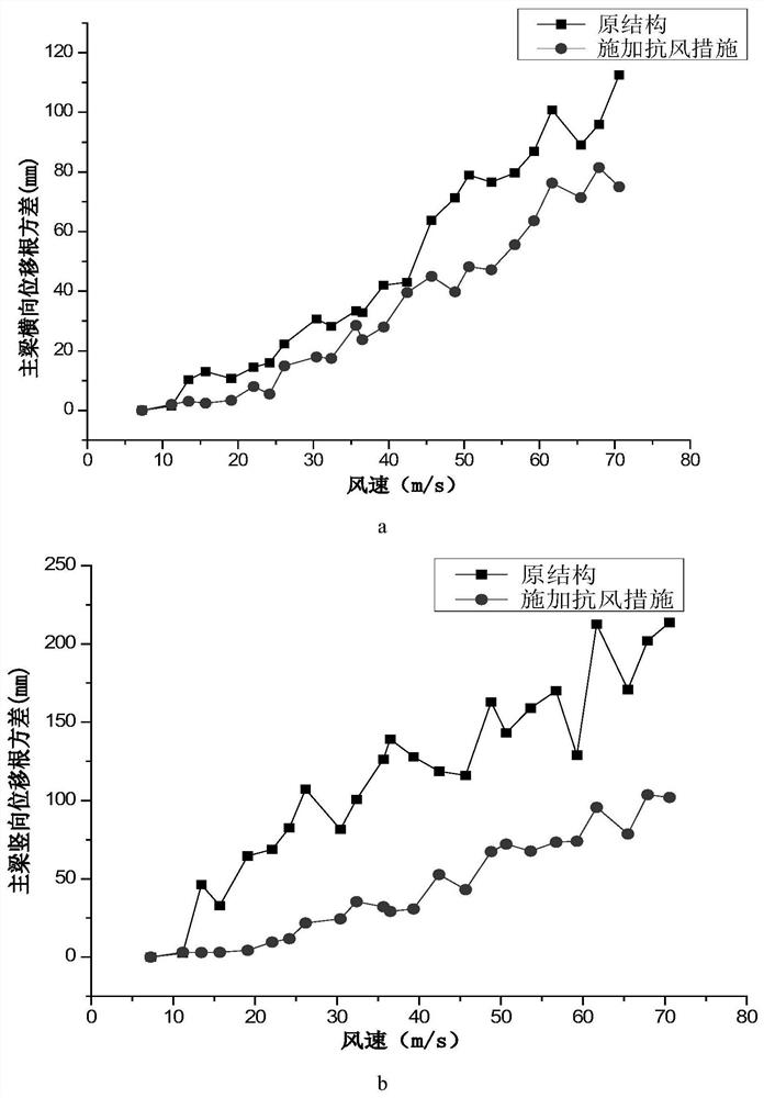
However, the single down-cable measure and TMD measure have relatively large wind-induced vibration response and wind-induced buffeting load during the construction period of the main girder of the bridge structure, resulting in poor wind-resistant safety and construction personnel comfort during the bridge construction period; in addition, the inclined down-cable In the scheme, the inherent damping of the "swaying main beam" mode of the main beam is relatively low, resulting in a small lateral stiffness of the beam; and the problem of low stiffness of the "overall vertical pendulum" of the main beam

Method used


Image

  • Wind-induced vibration control method for high-pier long-span bridge during construction period
  • Wind-induced vibration control method for high-pier long-span bridge during construction period
  • Wind-induced vibration control method for high-pier long-span bridge during construction period

Examples


Embodiment

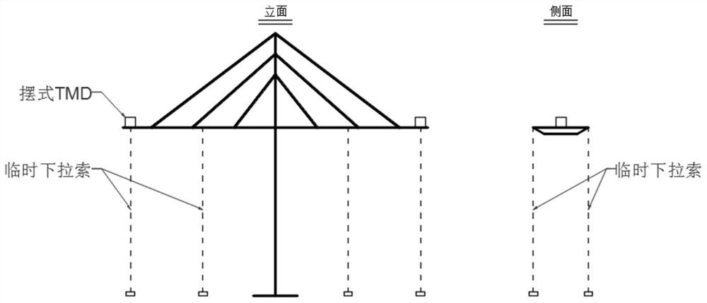
[0061] Example: A wind-induced vibration control method during the construction period of a high-pier long-span bridge, such as figure 1 shown, including the following steps:

[0062] S101: Analyze the dynamic characteristics of the cantilever structure of the main beam of the high-pier long-span bridge during the construction period, and obtain the natural frequency information of the first 20 orders of the main beam at different construction stages;

[0063] S102: Establishing the original finite element model of the construction state of the main girder cantilever of the bridge structure according to the bridge structure design parameters and construction plan data;

[0064] S103: Obtain the wind resistance measure parameters for the cooperation between the vertical pull cable and the eddy current pendulum TMD, and input the wind resistance measure parameters into the original finite element model to establish the wind resistance finite element model;

[0065] S104: After ...


PUM


Abstract

The invention discloses a wind-induced vibration control method for a high-pier long-span bridge during a construction period, and relates to the technical field of civil engineering, and the main points of the technical scheme are that the method comprises the following steps: analyzing and obtaining inherent frequency information of a main beam; establishing an original finite element model; establishing a wind-resistant finite element model; carrying out structural dynamic characteristic complex modal analysis; evaluating and analyzing the complex modal dynamic characteristic result from the structure frequency and the modal damping ratio to obtain a first vibration reduction effect; performing evaluating and analyzing according to the buffeting response calculation result to obtain a second damping effect; verifying the test result of the wind-induced vibration response to obtain verification data; and correcting the elastic modulus of the bridge tower and girder concrete of the original finite element model according to the verification data. According to the method, wind-induced vibration control in the construction period of the main beam is carried out by adopting a wind-resistant measure that the vertical lower inhaul cable is matched with the swing type TMD, the wind-induced vibration response and the wind-induced buffeting load in the construction period of the main beam of a bridge structure can be effectively reduced, and the wind-resistant safety in the construction period of a bridge and the comfort of constructors are improved.

Description

technical field [0001] The invention relates to the technical field of civil engineering, more specifically, it relates to a method for controlling wind-induced vibration during the construction period of a high-pier long-span bridge. Background technique [0002] With the further advancement of my country's transportation infrastructure construction, the construction of large-scale bridges across bays and mountainous canyons will gradually become the focus of my country's long-span bridge construction at present and in the future. In the past two decades, my country has built a large number of long-span bridges in mountainous areas, such as Baling River Bridge, Beipan River Bridge, Sidu River Bridge, Aizhai Bridge, Chishi Super Bridge, Kaizhou Lake Super Bridge, Fenglin Super Bridge, etc. . The problem of wind characteristics and wind-induced vibration of the bridge position of high-pier long-span bridges in mountainous areas is more prominent, which is one of the key point...

Claims


Application Information

Patent Timeline
IPC IPC(8): G06F30/23E01D21/00G06F30/13
CPCG06F30/23G06F30/13E01D21/00G06F2119/14
Inventor 刘志文陈政清龚平龙海滨资道铭魏子然
Owner 湖南省潇振工程科技有限公司
Learn More