Connector and connector assembly using same

A technology for connectors and contact parts, which is applied to the parts, connections, and protective grounding/shielding devices of connecting devices. Shielding mesh and other issues to prevent movement and offset, enhance the shielding effect, and make installation less difficult

Active Publication Date: 2021-06-04
CHINA AVIATION OPTICAL-ELECTRICAL TECH CO LTD
View PDF16 Cites 0 Cited by
  • Summary
  • Abstract
  • Description
  • Claims
  • Application Information

AI Technical Summary

Problems solved by technology

[0005]The existing problems of the connector are: there are many constraints on the installation of the shielding net, and the requirements for the overall size of the shielding net as well as the position size and inner diameter of each hole are relatively high , a slight deviation will cause the shielding net to b...

Method used


Image

  • Connector and connector assembly using same
  • Connector and connector assembly using same
  • Connector and connector assembly using same

Examples


specific Embodiment 1

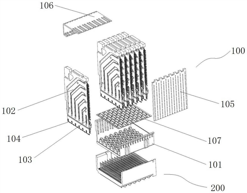
[0102] Such as figure 1 As shown, the connector assembly includes a female connector 100 and a male connector 200 that are mated to each other. Here, whether it is the female connector 100 or the male connector 200, the end used for insertion is the front end. .

[0103] The female end connector 100 includes a female end housing 101 and a plurality of terminal modules 102 arranged on the female end housing 101, wherein the terminal module 102 has a mounting end 103 and a mating end 104, and the mounting end 103 is used for fixed installation on a printed circuit board. On the board, the mating end 104 is used for mating with the male end connector 200 . The terminal modules 102 are generally square plates, and the terminal modules 102 are arranged in sequence along the thickness direction of the terminal modules 102 .

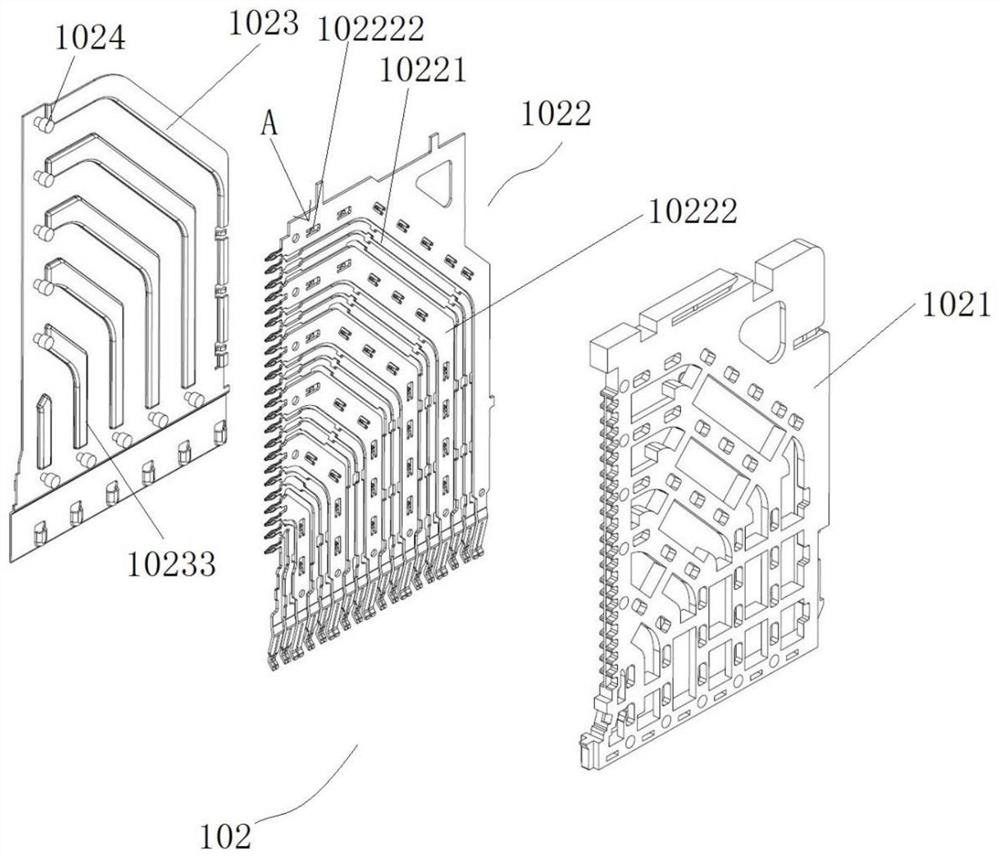
[0104] The structure of the terminal module 102 is as Figure 2 to Figure 10 As shown, the terminal module 102 includes a support frame 1021 , a terminal pa...

Embodiment 1

[0134] In Embodiment 1, the transverse shielding body is a transverse shielding sheet whose thickness direction is longitudinal. In this embodiment, the shape of the lateral shielding body can be changed, for example, it can be a columnar structure, and its cross section can be circular, square or other irregular shapes, the purpose of which is to separate two adjacent terminal rows.

[0135] Likewise, in Embodiment 1, the longitudinal shielding body is a longitudinal shielding sheet whose thickness direction is transverse. In this embodiment, the shape of the longitudinal shielding body can be changed, for example, it can be a columnar structure, and its cross-section can be circular, square or other irregular shapes. The purpose is to electrically connect each horizontal shielding body to form a complete common ground loop.

specific Embodiment 3

[0137] In Embodiment 1, there are two longitudinal shields, and the two longitudinal shields are located at both ends of each transverse shield. In this embodiment, there may be only one longitudinal shield, or the longitudinal shield may be omitted.


PUM


Abstract

The invention relates to the technical field of communication equipment, in particular to a connector and a connector assembly using the same, the connector comprises a connector shell and terminal rows, each terminal row comprises signal differential pairs and grounding terminals, the signal differential pairs and the grounding terminals are sequentially and alternately arranged in the transverse direction, each signal differential pair comprises a pair of signal terminals, at least two terminal rows are arranged at intervals along the longitudinal direction; the connector further comprises a shielding structure, the shielding structure comprises transverse shielding bodies fixedly arranged on the connector shell, the transverse shielding bodies are arranged between any two adjacent terminal rows, the transverse shielding bodies and the terminal rows are arranged at intervals in the longitudinal direction, and at least one side of each transverse shielding body in the longitudinal direction is provided with a transverse shielding body contact part in a protruding mode. And the transverse shielding body contact parts are used for being in contact conduction with the corresponding grounding terminals. The transverse shielding bodies do not need to be sleeved on the grounding terminals when being installed, can be installed independently from the grounding terminal, are not restrained by the grounding terminals, and are easy to install.

Description

technical field [0001] The invention relates to the technical field of communication equipment, in particular to a connector and a connector assembly using the connector. Background technique [0002] With the upgrade of the communication rate, the system puts forward more stringent requirements on the high-speed electrical performance indicators of the connector, among which the most critical electrical performance indicators are crosstalk, loss and reflection. [0003] For this reason, the Chinese invention patent application with the application publication number CN109473805A has designed a connector and backplane interconnection system, wherein the connector includes a connector housing, and at least two rows of terminals are fixedly mounted on the connector housing. Each terminal row includes ground terminals and signal differential pairs arranged alternately in sequence, and the signal differential pair includes two signal terminals. In order to improve the electrica...

Claims


Application Information

Patent Timeline
IPC IPC(8): H01R13/6581H01R13/652H01R13/6471
CPCH01R13/6581H01R13/652H01R13/6471
Inventor 李宗蔚
Owner CHINA AVIATION OPTICAL-ELECTRICAL TECH CO LTD
Why Eureka
Try Eureka