
Rotor magnetic pole modulation induction hybrid excitation brushless motor and power generation system

A hybrid excitation and rotor magnetic pole technology, applied in the direction of controlling generators, magnetic circuits, and electromechanical devices through magnetic field changes, can solve problems such as reducing the utilization rate of permanent magnet materials and increasing eddy current losses, reducing the risk of demagnetization and reducing eddy current losses. , The effect of high magnetic adjustment efficiency

Active Publication Date: 2022-03-25
NANJING UNIV OF AERONAUTICS & ASTRONAUTICS
View PDF6 Cites 0 Cited by
  • Summary
  • Abstract
  • Description
  • Claims
  • Application Information

AI Technical Summary

Problems solved by technology

[0005] However, the existing rotor permanent magnet type (permanent magnet is located in the rotor) hybrid excitation motor also introduces an additional magnetic circuit while realizing the parallel relationship between the permanent magnet and the electric excitation magnetic potential
The permanent magnetic flux is short-circuited through the additional magnetic circuit, forming magnetic flux leakage, which reduces the utilization rate of permanent magnetic materials
Moreover, most of the additional magnetic circuits are solid magnetic conductive parts, which increases the eddy current loss

Method used


Image

  • Rotor magnetic pole modulation induction hybrid excitation brushless motor and power generation system
  • Rotor magnetic pole modulation induction hybrid excitation brushless motor and power generation system
  • Rotor magnetic pole modulation induction hybrid excitation brushless motor and power generation system

Examples


Embodiment Construction

[0055] The present invention will be further described in detail below in conjunction with the accompanying drawings and specific preferred embodiments.

[0056]In the description of the present invention, it should be understood that the orientations or positional relationships indicated by the terms "left side", "right side", "upper", "lower" are based on the orientations or positional relationships shown in the accompanying drawings, and are only For the purpose of describing the present invention and simplifying the description, rather than indicating or implying that the device or element referred to must have a specific orientation, be constructed and operate in a specific orientation, "first", "second" and the like do not represent components importance, and therefore should not be construed as limiting the invention. The specific dimensions used in this embodiment are only for illustrating the technical solution, and do not limit the protection scope of the present inv...


PUM


Abstract

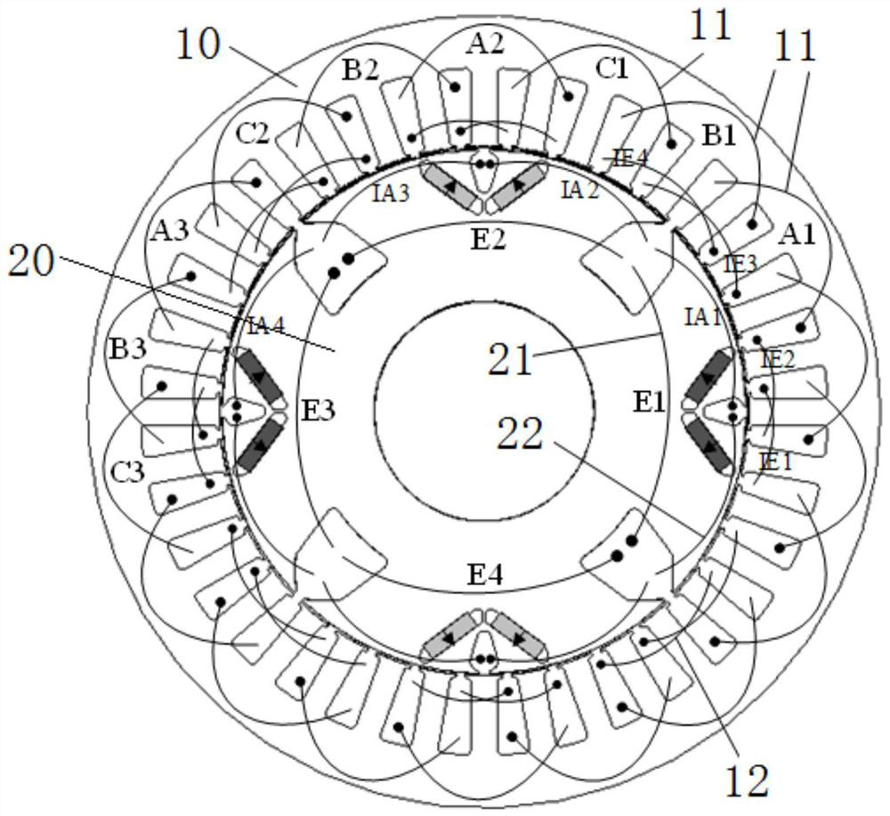
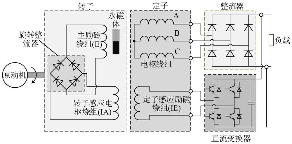
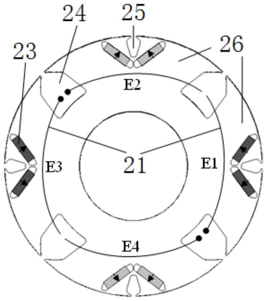
The invention discloses a rotor magnetic pole modulation type induction hybrid excitation brushless motor and a power generation system, comprising a stator, a magnetic pole modulation type rotor, an armature winding, an induction excitation winding, a main excitation winding, an induction armature winding and a rotary rectifier; Both the winding and the induction field winding are set in the stator; the main field winding and the induction armature winding are both set in the magnetic pole modulation type rotor; the main field winding is connected with the induction armature winding through the rotating rectifier; the magnetic pole modulation type rotor includes along the circumferential direction k repeated magnetic pole units, where k is a positive integer; the number of pole pairs of each magnetic pole unit is p 0 , then the number of pole pairs of the magnetic pole modulation rotor p = k×p 0 , p 0m =n, p 0i =n+1, n is a positive integer. The invention adopts the magnetic pole modulation type rotor, and the single main excitation coil can be adjusted at the same time p 0i The magnetic flux of each core pole is high, and the magnetic adjustment efficiency is high. At the same time, the brushless power supply of the main excitation winding on the rotor can be realized, and the induction efficiency can be improved. In addition, the self-excitation of the motor can be realized without the need for an external power supply.

Description

technical field [0001] The invention relates to the field of motor design and manufacture, in particular to a rotor magnetic pole modulation induction hybrid excitation brushless motor and a power generation system. Background technique [0002] Permanent magnet motors have the advantages of high torque / power density, high efficiency and high power factor, and have been applied in many occasions. However, field weakening of PM motors is achieved by controlling the direct-axis current component in the armature winding (-i d ) to achieve, the permanent magnet has the risk of irreversible demagnetization, and the weakening capacity is limited. [0003] In the case of constant voltage power generation, the permanent magnet motor needs a full-power controllable converter to stabilize the output voltage. The weight and cost of the system are too high, and the voltage stabilization requires position information and the control is complicated. [0004] The hybrid excitation motor ...

Claims


Application Information

Patent Timeline
Patent Type & Authority Patents(China)
IPC IPC(8): H02K1/22H02K1/276H02K1/12H02P9/30
CPCH02K1/223H02K1/274H02K1/12H02P9/30
Inventor 李健王凯
Owner NANJING UNIV OF AERONAUTICS & ASTRONAUTICS
Learn More