Maximum power point tracking analog control circuit applied to micro inverter

A maximum power point, micro-inverter technology, applied in circuit devices, AC network circuits, control/regulation systems, etc. Effects of Control Cost and Complexity, Reduced Simulation Control Cost, Reduced System Control Cost and Complexity

Pending Publication Date: 2021-06-04
ZHEJIANG UNIV
View PDF5 Cites 0 Cited by
  • Summary
  • Abstract
  • Description
  • Claims
  • Application Information

AI Technical Summary

Problems solved by technology

The maximum power point tracking analog control circuit in the existing research and development results usually adopts a control strategy specially designed for the micro-inverter system; but these are only applicable to the DC system and are suitable for the maximum power point analog control technology of the micro-inverter not yet well studied

Method used


Image

  • Maximum power point tracking analog control circuit applied to micro inverter
  • Maximum power point tracking analog control circuit applied to micro inverter
  • Maximum power point tracking analog control circuit applied to micro inverter

Examples


Embodiment Construction

[0044] Embodiments of the present invention will be described in detail below in conjunction with the accompanying drawings.

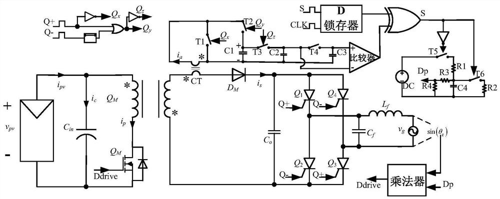
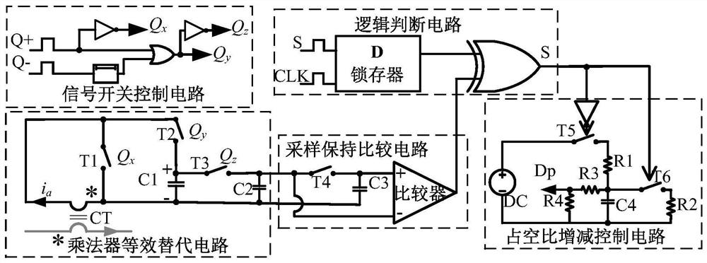
[0045] figure 1 It is a schematic diagram of the maximum power point tracking analog control circuit of the present invention, and is the core content of the present invention. It mainly includes a multiplier equivalent replacement circuit, a signal switch control circuit, a sample-and-hold comparison circuit, a logic judgment circuit, and a duty cycle increase / decrease control circuit. The output voltage of the equivalent replacement circuit of the multiplier is proportional to the output power of the photovoltaic panel; the voltage outputs a high and low level signal after passing through the sample-and-hold comparison circuit to indicate the increase or decrease of the output power of the photovoltaic panel, and a high level indicates the decrease in the output power of the photovoltaic panel. Low level indicates that the output power of the photo...


PUM


Abstract

The invention relates to the technical field of power electronic application, and aims to provide a maximum power point tracking analog control circuit applied to a micro inverter. The micro inverter connected to the photovoltaic cell panel comprises a flyback converter and a full-bridge power frequency inverter, and the maximum power point tracking analog control circuit is used for controlling the flyback converter. The control circuit comprises a signal switch control circuit, and a multiplier equivalent replacement circuit, a sampling and holding comparison circuit, a logical judgment circuit and a duty ratio increase and decrease control circuit which are electrically connected in sequence. Logic judgment is carried out on output power changes and duty ratio changes of the photovoltaic cell panel, then the duty ratio is directly controlled, and finally maximum power point tracking of the photovoltaic cell panel is achieved step by step. According to the invention, simulation control of maximum power point tracking in the micro-inverse system can be realized step by step, the control cost and complexity of the maximum power point of the photovoltaic cell panel can be effectively reduced, and the control of the micro-inverse system can be further integrated.

Description

technical field [0001] The invention belongs to the technical field of power electronics application and relates to the maximum power point tracking control of a photovoltaic cell panel. Background technique [0002] With the reduction of traditional fossil energy reserves and the increasing difficulty of mining, and the reduction of the application cost of various renewable energy sources, human beings have generally increased the research and application of renewable energy. Among them, solar energy has become a hot spot in the application research of renewable energy due to its advantages such as wide distribution, easy access, zero emission, and sustainability. [0003] For solar photovoltaic power generation technology, there are mainly two types of applications: centralized and distributed. Among them, the component-level photovoltaic power generation system in distributed applications has many advantages, and has gradually become a mainstream of research. Current so...

Claims


Application Information

Patent Timeline
IPC IPC(8): H02M7/162H02M1/06H02M3/335H02J3/38
CPCH02J3/381H02M1/06H02M3/335H02M7/162H02J2300/26Y02E10/56
Inventor 陈敏傅钰泰郑睿瑞齐继志韩放
Owner ZHEJIANG UNIV
Why Eureka
Try Eureka