Clutch and compressor comprising same

A clutch and compressor technology, applied in clutches, magnetic drive clutches, non-mechanical drive clutches, etc., can solve the problems of noise, vibration, attenuation, etc.

Active Publication Date: 2021-06-04
HANON SYST
View PDF16 Cites 0 Cited by
  • Summary
  • Abstract
  • Description
  • Claims
  • Application Information

AI Technical Summary

Problems solved by technology

[0015] However, in such a conventional clutch and a compressor including the clutch, noise and vibration are generated due to contact and separation between the pulley and the disc, but there is a problem that it cannot be damped
[0016] That is, there is considerable noise and vibration generated when the pulley collides with the disk, and noise and vibration generated when the pulley rotates together in a state in contact with the disk is transmitted to the compressor, and the problem of considerable noise and vibration due to the repulsive force of the disc when the pulley is separated from the disc

Method used


Image

  • Clutch and compressor comprising same
  • Clutch and compressor comprising same
  • Clutch and compressor comprising same

Examples


Embodiment Construction

[0055] Hereinafter, a clutch according to the present invention and a compressor including the clutch according to the present invention will be described in detail with reference to the accompanying drawings.

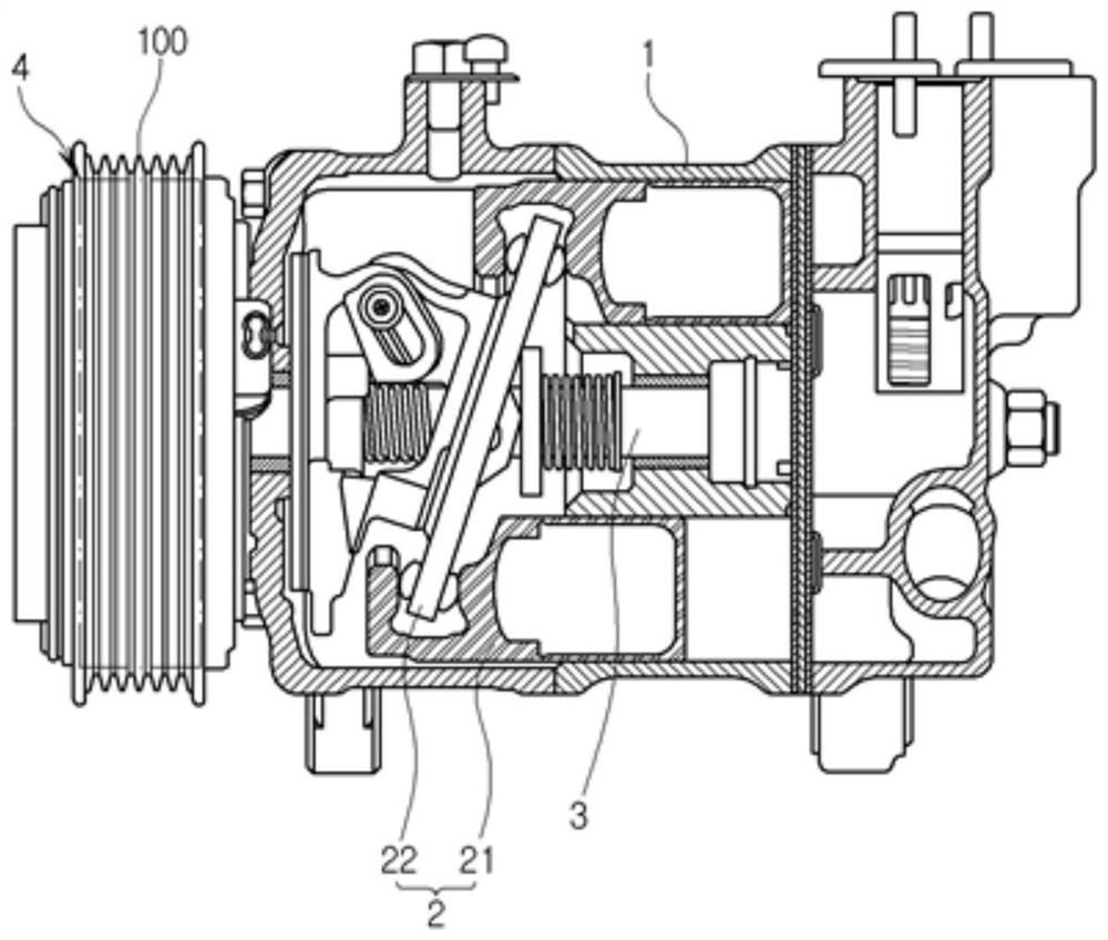
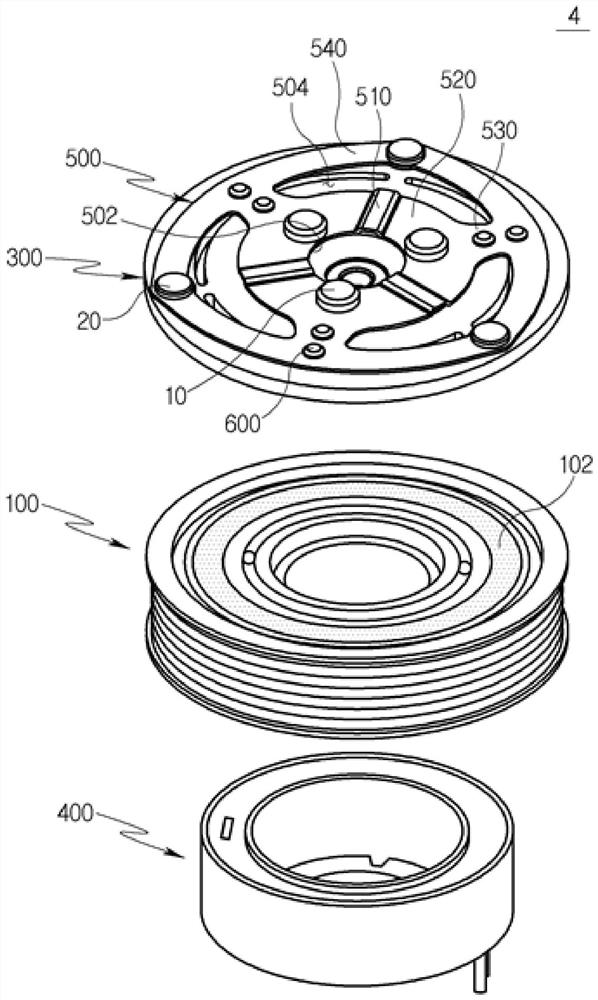
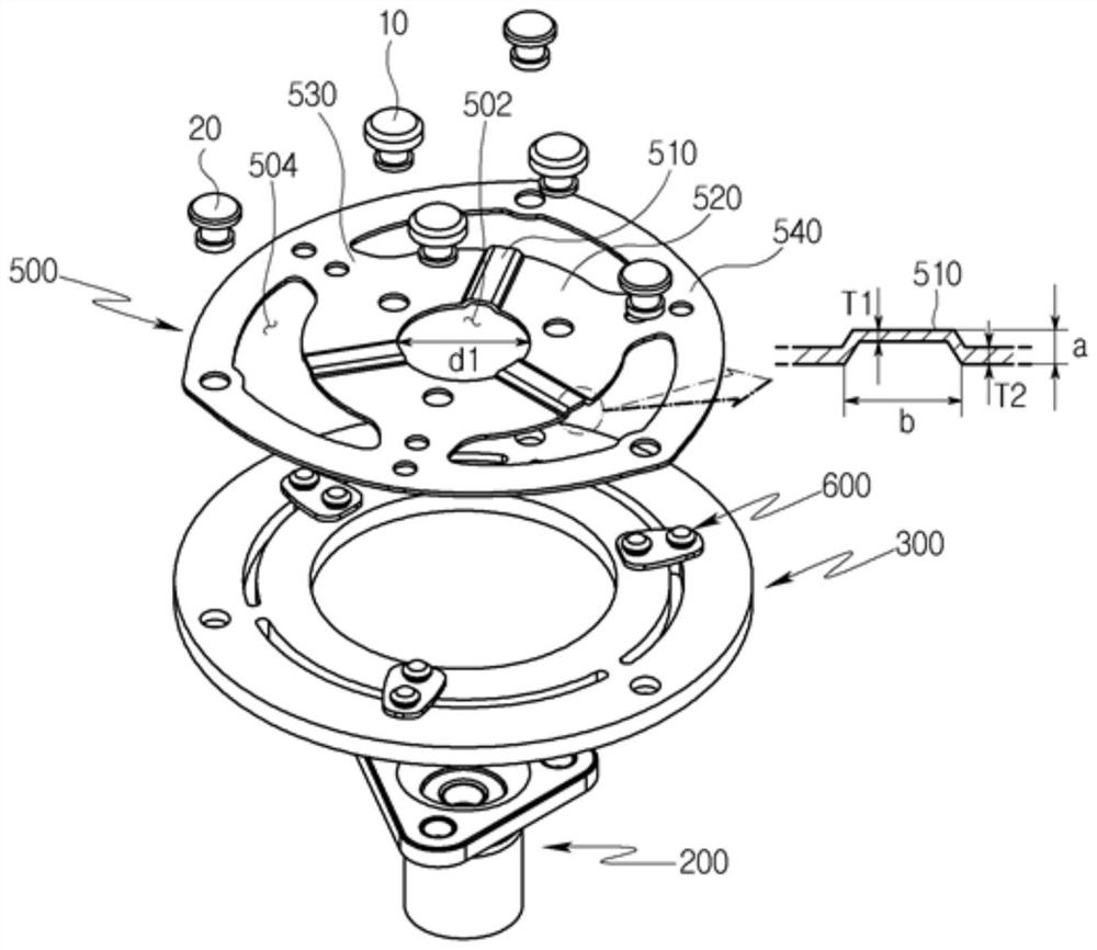
[0056] figure 1 is a sectional view showing a compressor including a clutch, figure 2 is an exploded perspective view showing the clutch according to the first embodiment of the present invention, and image 3 is showing figure 2 An exploded perspective view of the disc hub assembly.

[0057] A clutch according to a first embodiment of the present invention will be described with reference to the drawings.

[0058] Refer to the attached Figure 1 to Figure 3 , the clutch according to the first embodiment of the present invention minimizes the generation of vibration by increasing the rigidity to prevent the vibration transmitted in the shaft direction of the clutch due to the vibration caused by the compressor provided in the vehicle during operation. The result...


PUM


Abstract

The present invention relates to a clutch and a compressor comprising the same, and provides a compressor which operates with low noise and low vibration by reducing an amplitude of vibration transmitted in the axial direction of a clutch.

Description

technical field [0001] The present invention relates to a clutch and a compressor including the clutch. More specifically, the present invention relates to a clutch that selectively connects and disconnects a drive source and a rotating shaft, and a compressor including the clutch. Background technique [0002] Generally, the vehicle is provided with an air conditioning device (Air Conditioning; A / C) for heating and cooling the air in the room. Such an air conditioner includes a compressor that compresses a low-temperature and low-pressure refrigerant supplied from an evaporator into a high-temperature and high-pressure refrigerant and sends it to a condenser. [0003] Compressors are classified into a reciprocating type that compresses refrigerant according to the reciprocating motion of a piston, and a rotary type that performs compression while performing a rotary motion. The reciprocating type is classified into a crank type that transmits to a plurality of pistons usin...

Claims


Application Information

Patent Timeline
Patent Type & Authority Applications(China)
IPC IPC(8): F16D27/112F16D27/118
CPCF16D27/112F16D27/118B60H1/3222F16D2300/22F16D27/108
Inventor 金世博
Owner HANON SYST
Why Eureka
Try Eureka