Sleeve-connection type numerical-control machine tool protective device and using method

A technology of CNC machine tools and protective devices, which is applied in the field of CNC machine tools, can solve problems such as worker burns, iron filings removal, and iron filings splashing, and achieve the effects of reducing labor intensity, preventing solidification, and preventing scratches

Inactive Publication Date: 2021-06-08
李婕
View PDF0 Cites 0 Cited by
  • Summary
  • Abstract
  • Description
  • Claims
  • Application Information

AI Technical Summary

Problems solved by technology

[0003] However, during the processing of the current CNC machine tools, a large amount of iron filings will splash on the guide rail. If it is not cleaned in time, it will cause scratches on the surface of the guide rail and affect the processing efficiency. Most of the existing cleaning methods are It is cleaned manually. This cleaning method is not only time-consuming and laborious, but may also cause iron filings to splash on the workers' skin and cause burns. At the same time, the existing CNC machine tools cannot regularly remove the iron filings, and workers need to do it manually. Cleaning up further increases the labor intensity of workers

Method used


Image

  • Sleeve-connection type numerical-control machine tool protective device and using method
  • Sleeve-connection type numerical-control machine tool protective device and using method
  • Sleeve-connection type numerical-control machine tool protective device and using method

Examples


Embodiment Construction

[0030] The following will clearly and completely describe the technical solutions in the embodiments of the present invention with reference to the accompanying drawings in the embodiments of the present invention. Obviously, the described embodiments are only some, not all, embodiments of the present invention. Based on the embodiments of the present invention, all other embodiments obtained by persons of ordinary skill in the art without making creative efforts belong to the protection scope of the present invention.

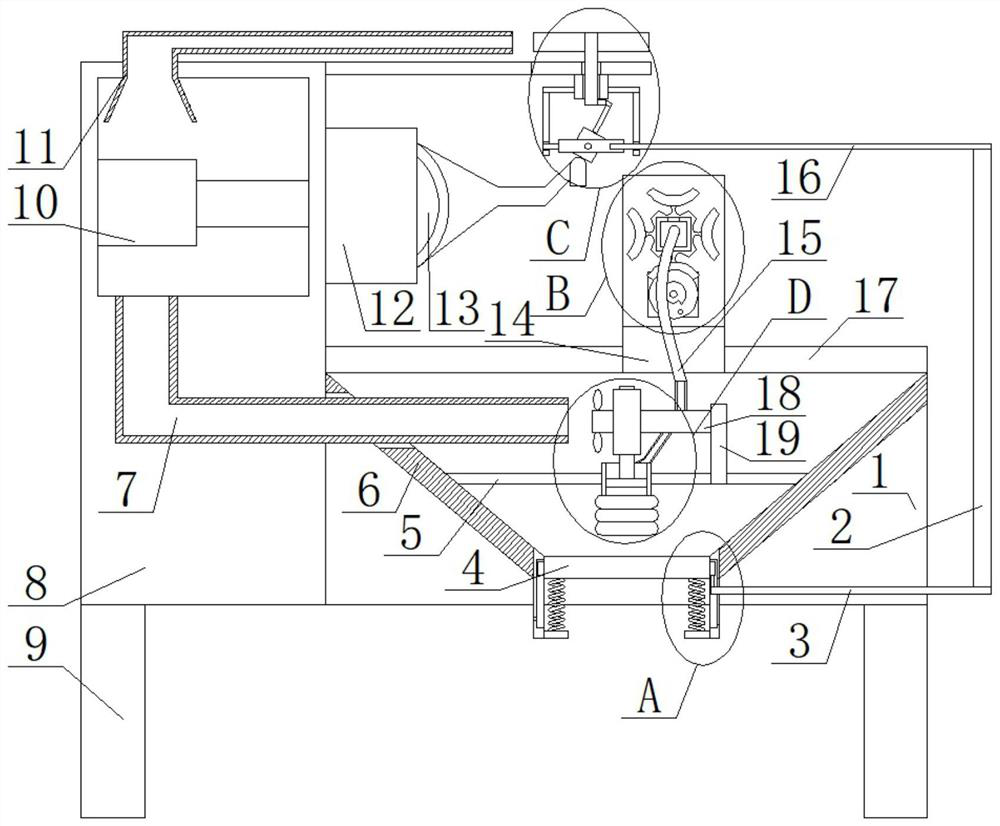
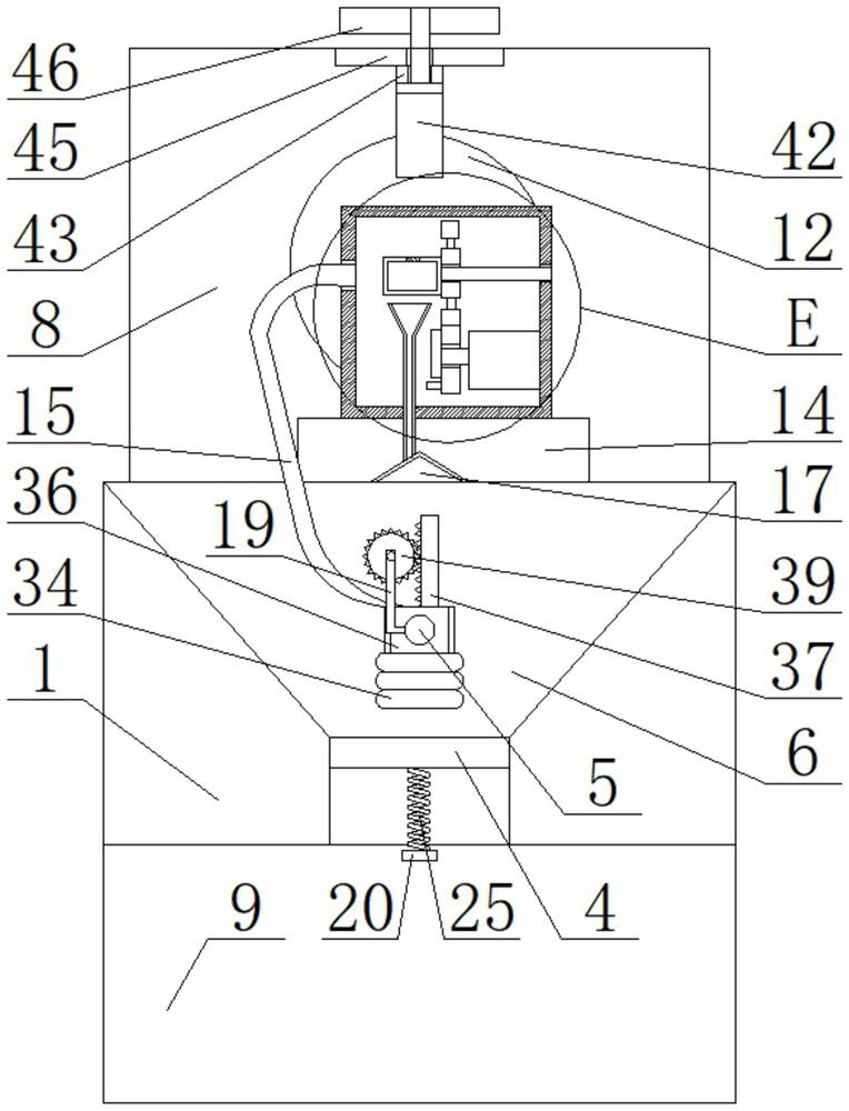
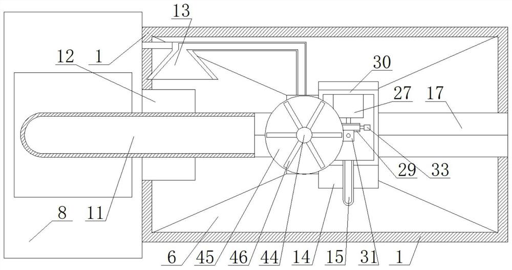
[0031] see Figure 1-8 , the present invention provides a technical solution: a sleeve-type CNC machine tool protection device and its use method, including a box 1 arranged horizontally, a first opening is opened on the top of the box 1, and a second opening is opened at the center of the bottom of the box 1. Two openings, there are two material guide plates 6 in the inner cavity of the box body 1, and the two material guide plates 6 are symmetrically arrange...


PUM


Abstract

The invention discloses a sleeve-connection type numerical-control machine tool protective device. The sleeve-connection type numerical-control machine tool protective device comprises a horizontal box body, wherein a first opening is formed in the top of the box body; a second opening is formed in the bottom center of the box body; two guide plates are arranged in the inner cavity of the box body; the two guide plates are symmetrically arranged left and right; front and rear sides of the two guide plates are fixedly connected onto adjacent side walls of the inner cavity of the box body; a tank body is arranged between the two guide plates; and transverse rods are fixedly connected to positions, close to the top, of left and right sides of the tank body; ends, away from the tank body, of the two transverse rods are fixedly connected onto adjacent guide plates. Through mutual matching of first movable plates, slide blocks, springs, first fixed plates and vertical rods, the automatic discharge purpose of iron chips can be realized, so that labor intensity of a worker is greatly reduced.

Description

technical field [0001] The invention relates to the technical field of numerical control machine tools, in particular to a socket-type numerical control machine tool protection device and a use method. Background technique [0002] Numerical control machine tool is the abbreviation of digital control machine tool. It is an automatic machine tool equipped with a program control system. It is input into the numerical control device through the information carrier, and after calculation and processing, the numerical control device sends out various control signals to control the movement of the machine tool. and dimensions, the parts are automatically machined out. [0003] However, during the processing of the current CNC machine tools, a large amount of iron filings will splash on the guide rail. If it is not cleaned in time, it will cause scratches on the surface of the guide rail and affect the processing efficiency. Most of the existing cleaning methods are It is cleaned ...

Claims


Application Information

Patent Timeline
IPC IPC(8): B23Q11/00B23Q11/08B23Q11/10
CPCB23Q11/005B23Q11/08B23Q11/10
Inventor 李婕
Owner 李婕
Why Eureka
Try Eureka