Buffer device for fully-closed dehydration pipeline of oil tank

A technology of buffer devices and dehydration pipes, which is applied in the direction of distribution devices, special distribution devices, liquid distribution, transportation or transfer devices, etc., and can solve problems such as sludge blockage, limited liquid flow, and oil passages that cannot meet the requirements of continuous and effective dehydration

Pending Publication Date: 2021-06-08
GUANGZHOU DAY WO AUTOMATION IND
View PDF0 Cites 0 Cited by
  • Summary
  • Abstract
  • Description
  • Claims
  • Application Information

AI Technical Summary

Problems solved by technology

[0004] Therefore, in order to solve the problem that the limited liquid flow in the pipeline cannot meet the requirements of continuous and effective de

Method used


Image

  • Buffer device for fully-closed dehydration pipeline of oil tank
  • Buffer device for fully-closed dehydration pipeline of oil tank
  • Buffer device for fully-closed dehydration pipeline of oil tank

Examples


Embodiment 1

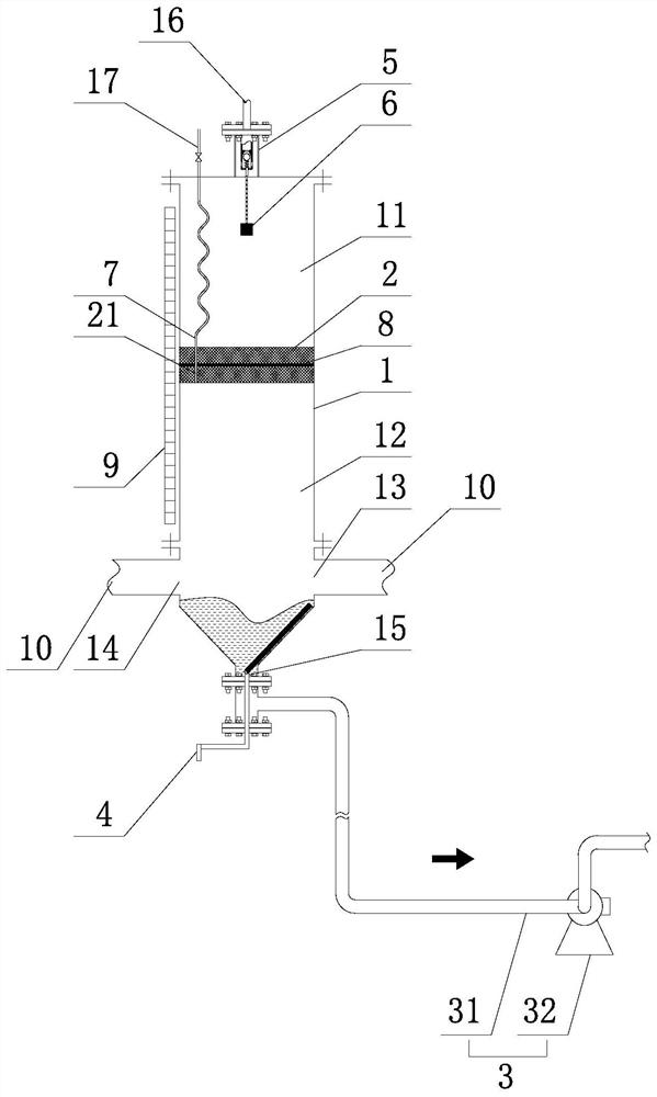
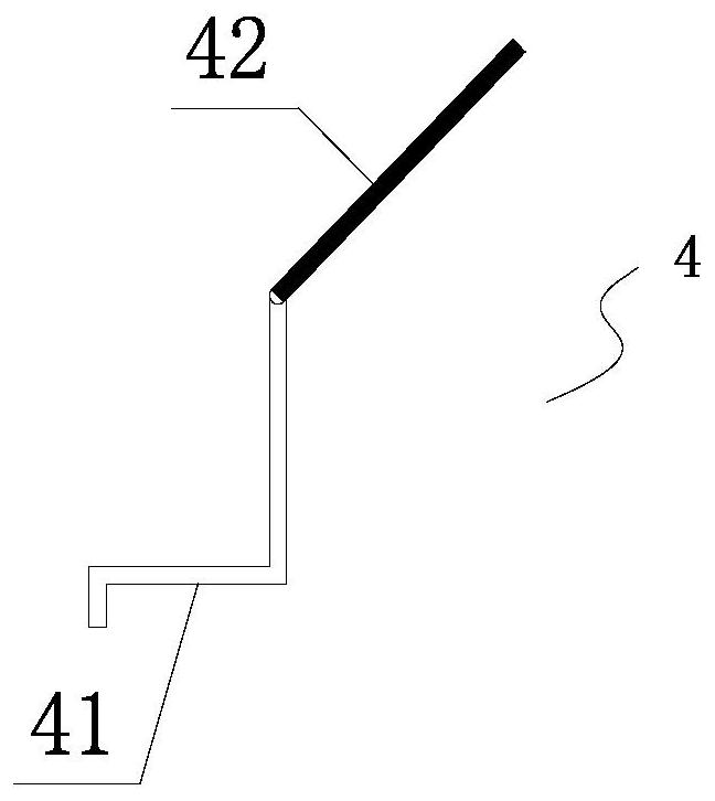
[0028] Such as figure 1 , figure 2 As shown, a buffer device for a fully enclosed dehydration pipeline of an oil tank according to the present invention includes a buffer tank 1 connected to a fully enclosed dehydration pipeline 10 of an oil tank. surface and divide the interior of the buffer tank 1 into upper and lower two independent areas of the sealing partition 2, the sealing partition 2 divides the interior of the buffer tank 1 into an upper buffer zone 11 and a lower liquid storage area 12, and the buffer tank 1 The side walls of the lower liquid storage area 12 are respectively provided with a water inlet 13 and a water outlet 14 communicated with the dehydration pipeline 10. The bottom of the buffer tank 1 is conical, and the bottom of the buffer tank 1 is provided with a sludge drain. Outlet 15, the sludge discharge port 15 is provided with a sludge recovery device 3, and the bottom of the buffer tank 1 is also provided with a sludge scraper device 4 capable of scr...

Embodiment 2

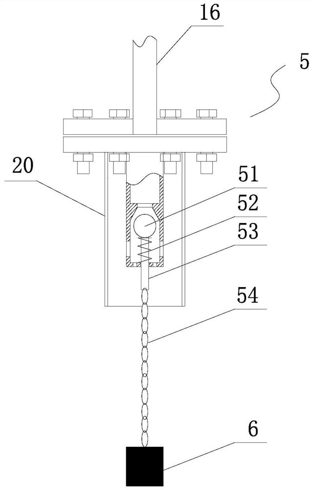
[0034] This embodiment is basically the same as Embodiment 1, the difference is: as Figure 4 As shown, the valve body of the switching valve assembly 5' is provided with a valve core 51' for blocking the breathing port 16, and the bottom of the valve core 51' is connected to a valve stem 53 equipped with a lever type touch switch 52' ', the end of the valve stem 53' is connected with a connecting chain 54', and a weight 6 is suspended from the end of the connecting chain 54'. The lever type touch switch 52' includes a lever hinged on the connecting block 20, one end of the lever is provided with a counterweight 521', the other end is provided with a sliding groove 522', and the end of the valve rod 53' It forms a sliding connection with the bottom of the sliding groove 522'. The sealing partition 2 will drive the weight 6 to lift the valve core 51' when the liquid level in the lower liquid storage area rises, and the valve core 51' will close the breathing port 16 after risi...


PUM


Abstract

The invention belongs to the technical field of petrochemical engineering, and particularly discloses a buffer device for a full-closed dehydration pipeline of an oil tank. The buffer device comprises a buffer tank communicating in the dehydration pipeline, a sealing partition plate capable of suspending on the liquid level and dividing the interior of the buffer tank into an upper independent area and a lower independent area is arranged inside the buffer tank, the interior of the buffer tank is divided into an upper buffer area and a lower liquid storage area by the sealing partition plate, a water inlet and a water outlet communicating with the dehydration pipeline are arranged on the side wall of the buffer tank, an oil sludge outlet is formed in the bottom of the buffer tank, and an oil sludge scraper device is further arranged at the bottom of the buffer tank. The buffer device can further intercept and recycle residual oil sludge, oil waste is reduced, meanwhile, the lower liquid storage area of the buffer tank can store sewage to be dehydrated in the pipeline, a sewage pump can conduct dehydration work continuously and effectively, the sealing partition plate is matched with the combined design of a switch valve assembly capable of automatically closing a breathing opening, sewage is prevented from being discharged from the breathing opening due to leakage of the sealing partition plate, and meanwhile, the strength requirement of the sealing partition plate is further reduced through the combined design.

Description

technical field [0001] The invention belongs to the technical field of petrochemical industry, in particular to a buffer device for a fully enclosed dehydration pipeline of an oil tank. Background technique [0002] In the prior art, the oil in the oil tank in the field of petrochemical technology will contain certain impurities such as water or sediment. After long-term storage, the water or sediment will settle to the bottom of the tank. In order to improve the purity of the oil, it is usually necessary to The matching dehydration device dehydrates impurities such as water or sediment in the oil tank. [0003] In addition, because the oil-water mixture in the oil tank contains a certain amount of toxic and harmful gases, if the dehydration treatment is not carried out in a closed space, the toxic and harmful gases will cause great pollution and harm to the air and soil. Therefore, it is necessary to The entire dehydration process is carried out in a fully enclosed space, ...

Claims


Application Information

Patent Timeline
IPC IPC(8): B67D7/78B08B9/087
CPCB08B9/087B67D7/78
Inventor 韩德福韩灏澜刘文
Owner GUANGZHOU DAY WO AUTOMATION IND
Why Eureka
Try Eureka