Intermittent cloth storage and centralized cloth discharging device for cloth dyeing and cloth circulation dyeing machine

A dyeing machine and cloth technology, which is applied to liquid/gas/vapor processing transmission, processing textile material carrier, liquid/gas/vapor jet propelling fabric, etc., can solve the problem of limited fluid action strength and range, and cloth action efficiency needs to be improved And other issues

Active Publication Date: 2021-06-08
福建宇邦纺织科技有限公司
View PDF14 Cites 1 Cited by
  • Summary
  • Abstract
  • Description
  • Claims
  • Application Information

AI Technical Summary

Problems solved by technology

This method adopts the external contact effect on the cloth to cause the cloth to unfold. Since the strength and range of the fluid acting on the cloth are limited, the nozzle at the end is more for the effect of secondary dyeing, and the effect of fully unfolding the cloth. Efficiency needs to be improved

Method used


Image

  • Intermittent cloth storage and centralized cloth discharging device for cloth dyeing and cloth circulation dyeing machine
  • Intermittent cloth storage and centralized cloth discharging device for cloth dyeing and cloth circulation dyeing machine
  • Intermittent cloth storage and centralized cloth discharging device for cloth dyeing and cloth circulation dyeing machine

Examples


Embodiment 1

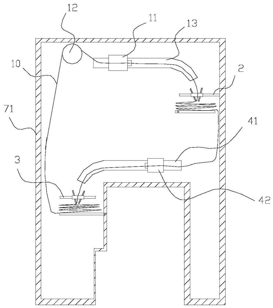
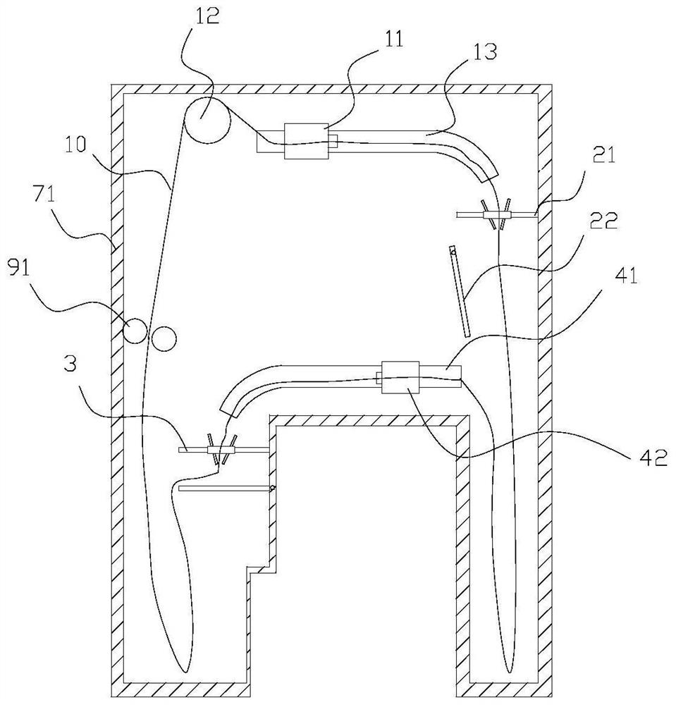
[0047] like figure 1 , 2 As shown, the present embodiment discloses a cloth circulation dyeing machine, which includes a primary nozzle 11, a cloth lifting device 12, and a primary cloth guiding pipe 13. The liquid energy drives the cloth 10 to move toward the outlet of the primary cloth guide pipe 13 .

[0048] It also includes a first intermittent cloth storage centralized cloth lowering device 2 , a second intermittent cloth storage concentrated lower cloth device 3 , a secondary cloth guide pipe 41 , and a secondary nozzle 42 . The first intermittent cloth storage centralized cloth lowering device 2 is used for reciprocating and stacking the cloth 10 falling from the outlet of the primary cloth guiding pipe 13 from bottom to top and intermittently collecting and lowering the cloth 10 stacked therein. The cloth 10 passing through the first intermittent cloth storage centralized cloth lowering device 2 can enter into the secondary cloth guiding pipe 41, and the dye liquor ...

Embodiment 2

[0085] like Figure 9-12 As shown, the difference between this embodiment and the above-mentioned embodiments is that this embodiment discloses a drive device with another structure, and the drive device includes a connecting plate 21481, a drive motor, a lower cloth rotating shaft 21461, a rotating rod 21482, and a driven slider 21483 , Drive rod 21484, drive slider 21485, intermittent gear transmission assembly.

[0086] The connecting plate 21481 is connected between the first fabric limiting plate 212 and the second fabric limiting plate 213, the first fabric limiting plate 212, the second fabric limiting plate 213, and the connecting plate 21481 form a whole, on the connecting plate 21481 A guide groove for up and down guidance is provided, and the driving slider 21485 is slidably matched with the guide groove in the vertical direction. The driving slider 21485 is hinged with the upper end of the rotating rod 21482, and the lower end of the rotating rod 21482 is fixedly ...

Embodiment 3

[0097] like Figure 13-15 As shown, the difference between this embodiment and the above-mentioned embodiments is: between the primary cloth guiding pipe 13 and the first intermittent cloth storage centralized cloth lowering device 2, the secondary cloth guiding pipe 41 and the second intermittent cloth storage centralized cloth lowering device 3 are also provided with a cloth stretching device 8, and the cloth stretching device 8 is used to spread the cloth 10 falling from the outlet of the corresponding cloth guide pipe.

[0098] The cloth stretching device 8 includes multiple groups of flattening assemblies arranged up and down, each group of flattening assemblies includes a first flattening rod 81, a second flattening rod 82, the lower end of the first flattening rod 81, the second flattening rod The lower end of 82 is rotatably engaged with the housing 71 . The upper end of the first flattening rod 81 and the upper end of the second flattening rod 82 are turned away from...


PUM


Abstract

The invention discloses an intermittent cloth storage and centralized cloth discharging device for cloth dyeing. A cloth swinging device is used for driving cloth falling from an outlet of a cloth guide pipe to do reciprocating motion and stacking the cloth on a corresponding cloth storage and discharging device from top to bottom; the cloth storage and discharging device comprises a cloth storage groove; a cloth discharging opening is formed in the cloth storage groove; a cloth discharging plate is rotationally matched with the cloth discharging opening; when the cloth discharging plate is horizontal, a cloth discharging gap exists between the cloth discharging plate and the cloth discharging opening, the swung cloth can be stacked on the cloth discharging plate, and the cloth located on the lowest layer of the cloth discharging plate can pass through the cloth discharging gap; the cloth discharging plate is turned downwards to enable the cloth stacked in the cloth discharging plate to fall downwards in a concentrated manner; and the cloth swinging device is linked with the cloth discharging plate, so that the cloth discharging plate completes one-time cloth discharging and resetting movement after the cloth swinging device drives the cloth to reciprocate for multiple times. The invention further discloses a cloth circulation dyeing machine. The intermittent cloth storage and centralized cloth discharging device has the advantages that the circulation space structure in the dyeing machine is optimized, the dyeing efficiency is improved, and the circulation stability and the dyeing quality of the cloth are guaranteed.

Description

technical field [0001] The invention relates to the technical field of textile dyeing and finishing, in particular to an intermittent cloth storage centralized cloth lowering device for cloth dyeing and a cloth circulation dyeing machine. Background technique [0002] The cloth cycle dyeing process is mainly to lift one end of the cloth to be dyed by the cloth lifting device, output it from the cloth guide pipe into the cloth storage tank, and then connect the end to the other end of the cloth to form a closed cloth loop. And under the action of the nozzle and the cloth lifting device, the circular dyeing is carried out. Certainly, in some technical schemes, as disclosed in CN210117510U, the dyeing machine without cloth guide wheel does not adopt the cloth lifting device, and realizes the circulation of the cloth ring with the nozzle as the driving source. [0003] After the cloth is output from the cloth guide pipe, it is temporarily stored in the cloth storage tank in the...

Claims


Application Information

Patent Timeline
IPC IPC(8): D06B3/28D06B3/34D06B23/04
CPCD06B3/28D06B3/34D06B23/04
Inventor 林泳安彭志洪王新盛张正清李威
Owner 福建宇邦纺织科技有限公司
Why Eureka
Try Eureka