
Silo and silo top structure thereof

A technology for silos and corridors, which is applied to roofs, building components, building structures, etc., and can solve problems such as installation difficulties, difficulty in meeting equipment deformation requirements, and inability to use roofing systems.

Pending Publication Date: 2021-06-08
CHINA POWER ENG CONSULTING GRP CORP EAST CHINA ELECTRIC POWER DESIGN INST
View PDF0 Cites 0 Cited by
  • Summary
  • Abstract
  • Description
  • Claims
  • Application Information

AI Technical Summary

Problems solved by technology

[0003] At present, silos generally adopt roof structures such as assembled conical shells and spherical shells. Since super-large silos often have a height of more than 50m, if roof structures such as assembled conical shells and spherical shells are used, because they are a space-combined stress system, The rigidity can only be exerted after the overall structure is completed, and a special construction method must be adopted, so the installation is very difficult
Moreover, due to the heavy load at the center, the cost is high, and it is difficult to meet the deformation requirements of equipment operation
If the reinforced concrete monolithic roof structure is used, it cannot be used for a roof system with a span of more than 30m due to its heavy weight and difficult construction
[0004] In related technologies, although there is a silo roof structure with a corridor trestle structure as the roof system of the core force-bearing component, the structural load is only transmitted from the roof closure system to the corridor system, and the structural system is a single force-bearing structural system. Unable to meet the deformation requirements of extremely high equipment operation on the roof of the storage structure under a super-long span

Method used


Image

  • Silo and silo top structure thereof
  • Silo and silo top structure thereof
  • Silo and silo top structure thereof

Examples


Embodiment Construction

[0030] The following will clearly and completely describe the technical solutions in the embodiments of the present invention with reference to the accompanying drawings in the embodiments of the present invention. Obviously, the described embodiments are only some, not all, embodiments of the present invention. Based on the embodiments of the present invention, all other embodiments obtained by persons of ordinary skill in the art without making creative efforts belong to the protection scope of the present invention.

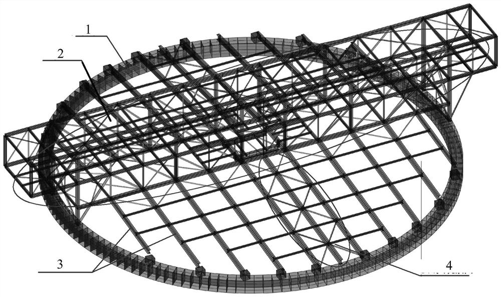
[0031] figure 1 is a perspective view of a roof structure of a silo according to an embodiment of the present invention. Such as figure 1 As shown, the warehouse roof structure includes: through ring beam 1, corridor truss 2, and solid web roof steel beam 3.

[0032] Among them, the penetrating ring beam 1 is set on the top of the silo; the corridor truss 2 is supported on the penetrating ring beam 1 through shear embedded parts; One end of the type roof st...


PUM


Abstract

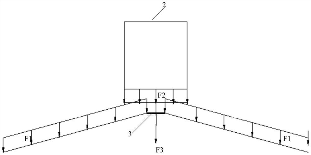
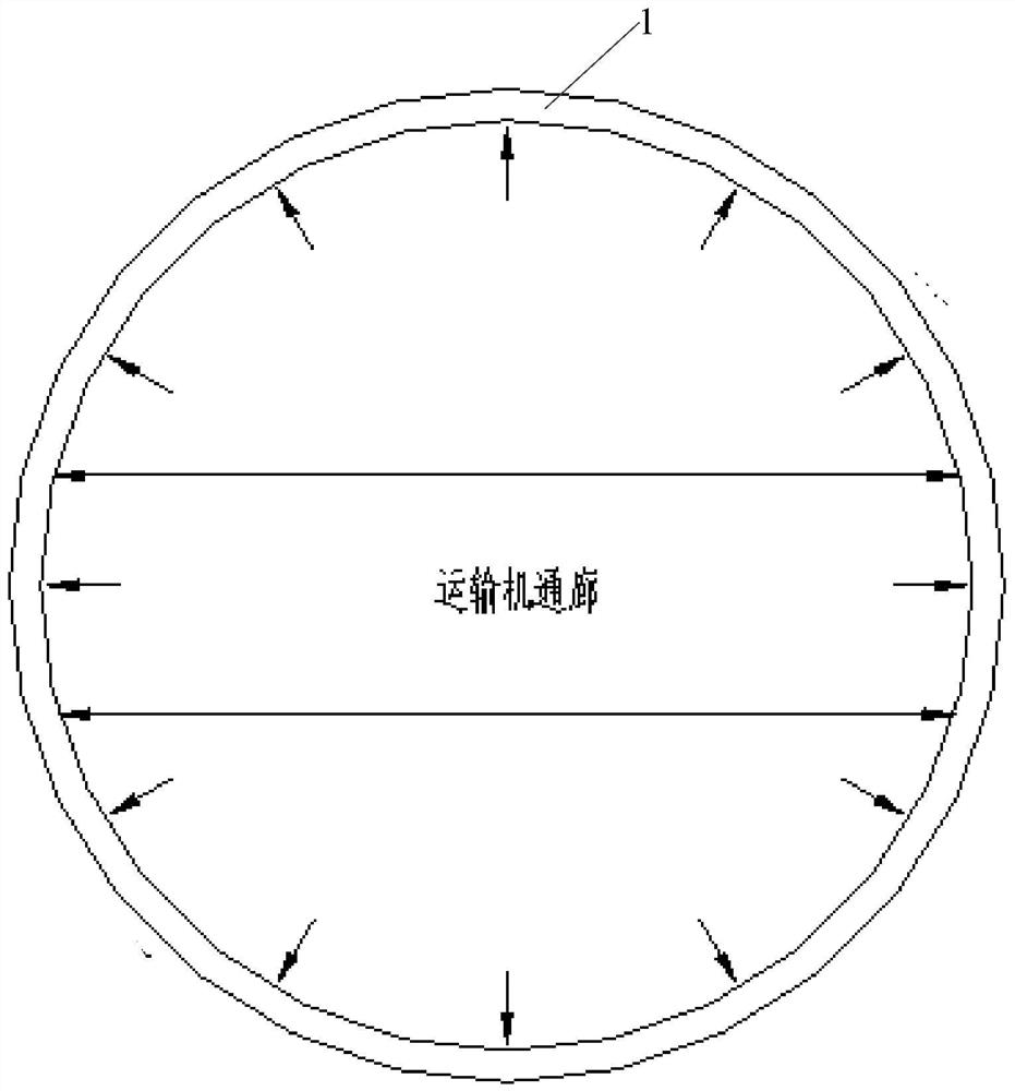
The invention provides a silo and a silo top structure thereof. The silo top structure comprises a through ring beam, a vestibule truss and solid-web roof steel beams, wherein the through ring beam is arranged at the top end of the silo; the vestibule truss is supported on the through ring beam through a shear-resistant embedded part; and the solid-web roof steel beams are symmetrically arranged in a fishbone mode along a center line of a vestibule, one ends of the solid-web roof steel beams are directly hinged to the lower chord of the vestibule truss, and the other ends of the solid-web roof steel beams are hinged to the through ring beams through reinforced concrete or steel buttresses. The vestibule trusses and the solid-web roof steel beams are combined into a whole, a vertical force resisting system of the roof is formed, the through ring beams at the top of the silo can weaken out-of-plane horizontal loads generated by a roof system, and local stress concentration of the silo wall structure can be relieved while the vertical deformation resisting capacity of the silo top structure is improved.

Description

technical field [0001] The invention relates to the technical field of roof structures, in particular to a silo roof structure and a silo. Background technique [0002] Due to the shortage of urban land, large-diameter silos with roof corridors have more and more practical significance. The storage capacity of a super-large silo can reach 100,000 cubic meters, and a super-large silo of 100,000 cubic meters has a diameter of about 55m and a height of more than 50m. [0003] At present, silos generally adopt roof structures such as assembled conical shells and spherical shells. Since super-large silos often have a height of more than 50m, if roof structures such as assembled conical shells and spherical shells are used, because they are a space-combined stress system, The rigidity can only be exerted after the overall structure is completed, and a special construction method must be adopted, so the installation is very difficult. And because the center is heavy and expensive...

Claims


Application Information

Patent Timeline
Patent Type & Authority Applications(China)
IPC IPC(8): E04H7/00E04B7/00E04B1/41
CPCE04B1/41E04B7/00E04H7/00
Inventor 苗毅王轩胡仕林
Owner CHINA POWER ENG CONSULTING GRP CORP EAST CHINA ELECTRIC POWER DESIGN INST
Learn More