An Annular and Radial Mixed Channel Magnetorheological Valve

A technology of radial mixing and magneto-rheological valves, applied in the field of magnetorheological valves, can solve problems such as pressure drop of magnetorheological valves, achieve the effects of reducing magnetic loss, improving performance, and increasing utilization efficiency

Active Publication Date: 2022-05-27
GUANGXI UNIVERSITY OF TECHNOLOGY
View PDF15 Cites 0 Cited by
  • Summary
  • Abstract
  • Description
  • Claims
  • Application Information

AI Technical Summary

Problems solved by technology

[0006] The purpose of the present invention is to provide a multi-coil magnetorheological valve, so as to solve the pressure drop of the existing magnetorheological valve due to the need for higher performance, so that the magnetorheological valve can be successfully used in various occasions with high pressure

Method used


Image

  • An Annular and Radial Mixed Channel Magnetorheological Valve
  • An Annular and Radial Mixed Channel Magnetorheological Valve

Examples


Embodiment 1

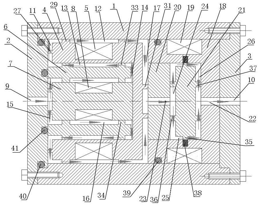
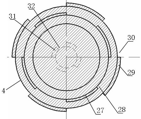
[0043] like Figure 1-2 As shown, the annular and radial mixed channel magnetorheological valve includes valve body 1, left end cover 2, right end cover 3, left coil support 4, left excitation coil 5, left magnetic conducting ring 6, left valve core 7. Left spool excitation coil 8;

[0044] Both ends of the valve body 1 are sealed by the left end cover 2 and the right end cover 3 respectively, the left end cover 2 is provided with a through hole a9 in the middle, and the right end cover 3 is provided with a through hole b10 in the middle;

[0045] The valve body 1 is divided into a left valve body and a right valve body;

[0046] The left coil support 4 is arranged in the inner wall of the valve body 1 and is located in the left valve body part; the left coil support 4 is a ring structure with a closed right end; the left end face of the left coil support 4 corresponds to On the right end face of the left end cover 2, there is a space between the left end face of the left co...


PUM


Abstract

The present invention aims to provide an annular and radial mixed channel magneto-rheological valve, including a valve body, a left end cover, a right end cover, a left coil support, a left excitation coil, a left magnetic guide ring, a left valve core, and a left valve core excitation coil; the two ends of the valve body are respectively sealed by the left end cover and the right end cover, the middle part of the left end cover is provided with a through hole a, and the middle part of the right end cover is provided with a through hole b; the valve body is divided into a left valve body and a right end cover. right valve body. The present invention solves the problem that the existing magneto-rheological valve needs higher performance and the pressure drop cannot satisfy the problem of stopping the operation of the whole system, so that the magnetorheological valve can be successfully used in various occasions with high pressure.

Description

technical field [0001] The invention relates to the field of magnetorheological valves, in particular to an annular and radial mixed channel magnetorheological valve. Background technique [0002] Compared with the traditional hydraulic control valve, the magnetorheological valve controls the flow of the magnetorheological fluid through the valve by controlling the magnitude of the excitation coil current. There are no moving mechanical parts. Compared with the traditional mechanical valve, the magnetic flow The variable fluid control valve has the advantages of simple structure, small size, easy control, fast response speed, low working noise, wear resistance, high reliability and low cost. Magnetorheological valves are now widely used. [0003] In engineering applications, magnetorheological fluids are often required to have different pressure drops in different flow directions, which are usually implemented in three ways: one is to use the controller to monitor the direc...

Claims


Application Information

Patent Timeline
Patent Type & Authority Patents(China)
IPC IPC(8): F16K47/04F16K31/06F16K27/00
CPCF16K47/04F16K31/0651F16K31/0675F16K27/00
Inventor 杨小龙张锐博何美丽
Owner GUANGXI UNIVERSITY OF TECHNOLOGY
Why Eureka
Try Eureka