Energy-saving comprehensive heat supply system

A technology of heating system and water supply tank, applied in heating system, heat recovery system, energy-saving heating/cooling, etc., can solve the problems of low utilization of heating heat energy, single heating equipment, waste of heat energy, etc.

Active Publication Date: 2021-06-08
贵州中能投科技有限公司
View PDF7 Cites 2 Cited by
  • Summary
  • Abstract
  • Description
  • Claims
  • Application Information

AI Technical Summary

Problems solved by technology

[0003] Aiming at the deficiencies of the existing technology, the technical problem solved by the present invention is to provide an energy-saving integrated heating system, which solves the problems of single central heating equipment, low heating heat energy utilization, and more heat energy waste in the prior art

Method used


Image

  • Energy-saving comprehensive heat supply system
  • Energy-saving comprehensive heat supply system

Examples


Embodiment 1

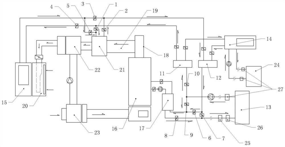
[0020] Embodiment 1 is basically as attached figure 1 Shown: an energy-saving comprehensive heating system, including heat user unit 13, boiler 16 heating unit, water source heat pump 14 heating unit, air energy heat pump 15 heating unit, heat recovery circulation unit, water tank, the water tank includes water supply tank 12 and return water tank 11. The heat recovery circulation unit is connected to the exhaust pipe 18 of the boiler 16 through the smoke introduction pipe 19, and the heat user unit 13 is connected to the heating unit of the boiler 16 through the water supply pipe and the return pipe to form the first heat supply circuit. The water supply pipe is detachably connected with The branch pipe of the water supply tank, one end of the branch pipe of the water supply tank is connected with the water outlet of the water supply tank, the return pipe can also be detachably connected with the branch pipe of the return water tank, and one end of the branch pipe of the retur...

Embodiment 2

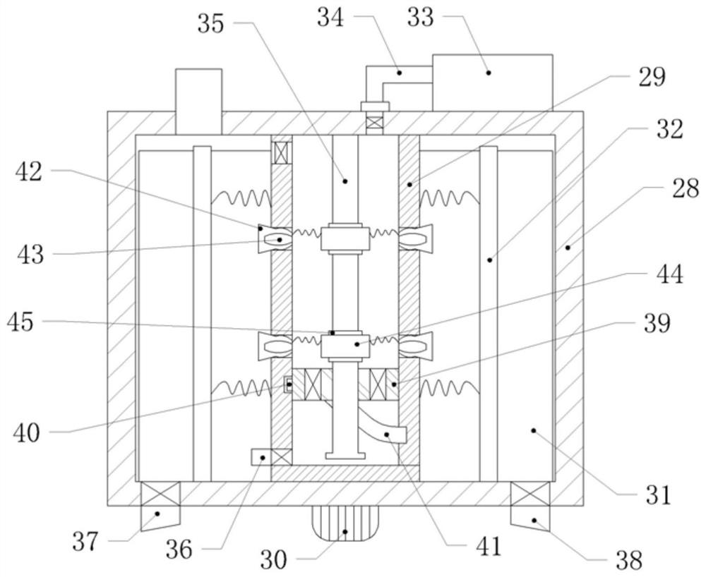
[0030] Example 2 as figure 2 As shown, the same parts as in Embodiment 1 will not be repeated. The above-mentioned water tank is provided with a descaling device. The descaling device includes a hollow rotating cylinder 29, a driving motor 30, a first scraper 31 and a scavenger box 33. The driving motor 30 is fixed on the The bottom of the box body 28 and the bottom of the rotating cylinder 29 are fixedly connected with the output shaft of the driving motor 30, the upper end of the rotating cylinder 29 is open and the upper surface of the opening is rotatably connected with the inner wall of the top plate of the water tank body 28, and the upper end of the rotating cylinder is provided with a first electric valve on the wall; The scavenger box 33 is arranged on the top of the water tank and is fixedly connected with the outer wall of the top plate of the water tank by bolts. The scavenger box 33 is connected with a scavenger pipe 34 by threads. Inside, the scavenger pipe is p...


PUM


Abstract

The invention relates to the technical field of heating equipment, and particularly discloses an energy-saving comprehensive heat supply system. The energy-saving comprehensive heat supply system comprises a heat consumer unit, a boiler heating unit, a water source heat pump heating unit, an air energy heat pump heating unit, a heat recovery circulating unit, a water return tank and a water supply tank. The heat recovery circulating unit is connected with a exhaust pipe of a boiler through a smoke pipe. The water supply tank is separately connected with the boiler heating unit, the water source heat pump heating unit and the air energy heat pump heating unit through a boiler water supply pipe, a water source heat pump water supply pipe and an air energy heat pump water supply pipe, and the heat recovery circulating unit is connected with the air energy heat pump water supply pipe through a heat recovery water supply pipe. The heat recovery circulating unit is connected with an air energy heat pump water return pipe through a heat recovery water return pipe. The energy-saving comprehensive heat supply system aims to solve the problems that in the prior art, central heating equipment is single, the utilization rate of heating heat energy is low, and more heat energy is wasted.

Description

technical field [0001] The invention relates to the technical field of heating equipment, in particular to an energy-saving comprehensive heating system. Background technique [0002] With the rapid development of society, more and more urban households have installed heating equipment. Most northern cities and communities adopt central heating. Existing heating equipment includes air conditioners, air source heat pumps, water source heat pumps, and boilers. Air conditioners are suitable for single families. For heating, air energy heat pumps, water source heat pumps and boilers are mainly suitable for large-area central heating; while in central heating, only one of air energy heat pumps, water source heat pumps and boilers is often used. When multiple heating equipment is used for heating, each heating equipment Insufficient use of heat energy between the two, poor heat recovery effect, resulting in waste of energy. Contents of the invention [0003] Aiming at the defic...

Claims


Application Information

Patent Timeline
Patent Type & Authority Applications(China)
IPC IPC(8): F24D12/02F24D19/10
CPCF24D12/02F24D19/1045F24D19/1015F24D2200/12Y02B30/52
Inventor 汪发增罗荣王东阳
Owner 贵州中能投科技有限公司
Why Eureka
Try Eureka