
Testing device

A testing device and elastic terminal technology, applied in the field of testing, can solve the problems of increasing resistance, affecting, weakening the transmission of electrical signal strength, etc.

Pending Publication Date: 2021-06-08
QUANWISE MICROELECTRONICS (ZHUHAI) CO LTD
View PDF0 Cites 1 Cited by
  • Summary
  • Abstract
  • Description
  • Claims
  • Application Information

AI Technical Summary

Problems solved by technology

[0002] In terms of test fixtures used for testing chips, connectors or other PCB boards (Printed Circuit Boardm, printed circuit boards), electrical signal conduction uses spring probes or elastic terminals with complex shapes to realize signal conduction. Due to the spring contacts in the internal mechanical structure of the probe, multi-point contact will be formed inside the probe, which will cause multiple contact resistances. The sum of multiple contact resistances will make the total resistance larger, especially when the probe has been used for a while. Over time, as the contacts wear, the resistance increases
In addition, the elastic force of the spring probe is achieved by the helical spring. The shape of the helical structure forms impedance or interference to the electrical signal, affecting and weakening the transmission of the electrical signal strength.
The complex S shape of the existing elastic terminal is provided by the elastic force provided by the laminated rotating structure similar to the spring structure, and this shape also has various impedances or interferences in electrical performance, which affects or weakens the electrical signal strength. transfer
With the continuous improvement of electrical signal communication technology, the requirements for the existing conductor resistance and interference are getting higher and higher. Spring probes and complex S-shaped elastic terminals cannot meet the requirements of electrical signal communication.

Method used


Image

  • Testing device
  • Testing device
  • Testing device

Examples


Embodiment Construction

[0025] This part will describe the specific embodiment of the present invention in detail, and the preferred embodiment of the present invention is shown in the accompanying drawings. Each technical feature and overall technical solution of the invention, but it should not be understood as a limitation on the protection scope of the present invention.

[0026] In the description of the present invention, it should be understood that the orientation descriptions, such as up, down, front, back, left, right, etc. indicated orientations or positional relationships are based on the orientations or positional relationships shown in the accompanying drawings, and are only In order to facilitate the description of the present invention and simplify the description, it does not indicate or imply that the device or element referred to must have a specific orientation, be constructed and operated in a specific orientation, and thus should not be construed as limiting the present invention...


PUM


Abstract

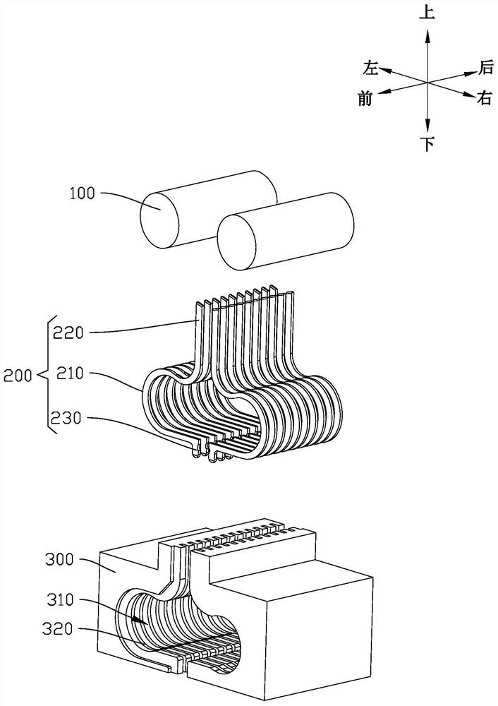
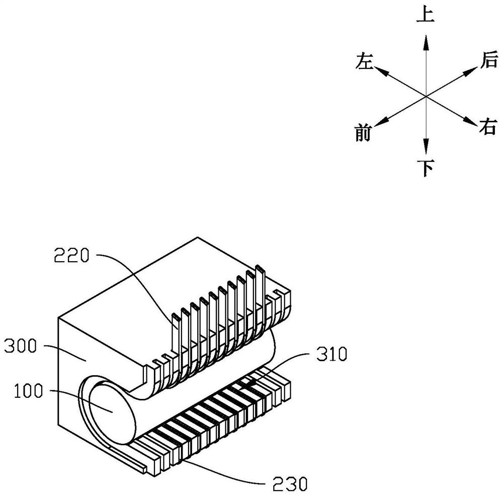
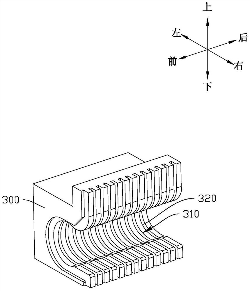
The invention relates to the technical field of detection, and discloses a testing device which is simple in structure and has no contact impedance inside. The testing device comprises an elastic piece, an elastic terminal provided with an arc-shaped elastic deformation part, and a terminal plate provided with a groove capable of accommodating the elastic piece, wherein the inner arc of the elastic deformation part is clamped on the corresponding elastic piece; and an arc-shaped groove matched with an elastic terminal is formed in the groove, the outer arc of the elastic deformation part is embedded in the arc-shaped groove, the upper end of the arc-shaped groove extends to the upper surface of the terminal plate, and the lower end of the arc-shaped groove extends to the lower surface of the terminal plate. According to the invention, the arc-shaped elastic terminal is utilized, so that an elastic recovery effect is achieved, the overall resistance can be prevented from being too large, the condition of contact impedance is avoided, and the interference is reduced; and a resilience force can be provided for the elastic terminal in cooperation with the elastic piece, the elastic service life of the elastic terminal is prolonged, the elastic terminal is fixed and isolated in cooperation with the terminal board, and meanwhile the assembling difficulty is simplified in cooperation with the clamping and embedding connection modes.

Description

technical field [0001] The invention relates to the technical field of detection, in particular to a testing device. Background technique [0002] In terms of test fixtures used for testing chips, connectors or other PCB boards (Printed Circuit Boardm, printed circuit boards), electrical signal conduction uses spring probes or elastic terminals with complex shapes to realize signal conduction. Due to the spring contacts in the internal mechanical structure of the probe, multi-point contact will be formed inside the probe, which will cause multiple contact resistances. The sum of multiple contact resistances will make the total resistance larger, especially when the probe has been used for a while. Over time, as the contacts wear, the resistance increases. In addition, the elastic force of the spring probe is achieved by the helical spring. The shape of the helical structure forms impedance or interferes with the electrical signal, affecting and weakening the transmission of...

Claims


Application Information

Patent Timeline
Patent Type & Authority Applications(China)
IPC IPC(8): G01R1/04G01R31/28G01R31/00
CPCG01R1/0416G01R31/28G01R31/2808G01R31/2818G01R31/00G01R1/0466G01R1/06716G01R1/07307
Inventor 黄光敏谢伟谢永康
Owner QUANWISE MICROELECTRONICS (ZHUHAI) CO LTD
Learn More