Refrigerant radiator, assembly design method and air conditioning equipment

A technology for refrigerant radiators and air-conditioning equipment, which is applied to lighting and heating equipment, heating methods, and electrical equipment structural components, etc., and can solve problems such as random installation positions and poor heat dissipation effects.

Pending Publication Date: 2021-06-08
GREE ELECTRIC APPLIANCES INC
View PDF0 Cites 0 Cited by
  • Summary
  • Abstract
  • Description
  • Claims
  • Application Information

AI Technical Summary

Problems solved by technology

[0004] Embodiments of the present invention provide a refrigerant radiator, an assembly design method, and air-conditioning equipment to solve the problem in the prior art that the installation positions of the refrigerant pipes of the refrigerant radiator are random, resulting in poor heat dissipation

Method used


Image

  • Refrigerant radiator, assembly design method and air conditioning equipment
  • Refrigerant radiator, assembly design method and air conditioning equipment
  • Refrigerant radiator, assembly design method and air conditioning equipment

Examples


Embodiment 1

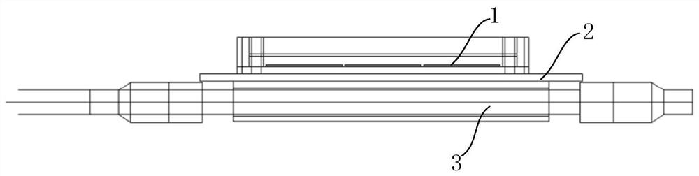
[0041] This embodiment provides a refrigerant radiator, which is applied to the heating module of the equipment. figure 1 It is a structural diagram of a refrigerant radiator according to an embodiment of the present invention, such as figure 1 As shown, the refrigerant radiator includes:

[0042] The cold plate 2 is stacked with the heating module 1 . A groove is provided on the surface of the cold plate 2 away from the heating module 1 to accommodate the refrigerant pipe 3 ; the refrigerant pipe 3 is embedded in the groove of the cold plate 2 .

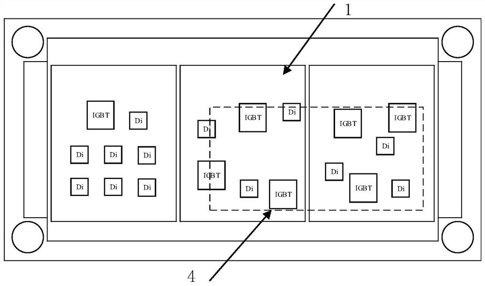
[0043] figure 2 It is a schematic diagram of the main heating area of ​​the heating module according to the embodiment of the present invention, such as figure 2 As shown, the distribution positions of the heating chips in the heating module 1 are not regular, and are unevenly distributed along the length direction of the heating module 1. On the whole, the main heating area 4 is mainly located in a certain concentrated area of ...

Embodiment 2

[0047] This embodiment provides another refrigerant radiator, which is applied to the heating module of the equipment. The heating module 1 is the frequency conversion module of the air conditioner. When the power or voltage of the heating module increases, the heating power will increase synchronously, so it needs to be replaced Efficient refrigerant cooling measures.

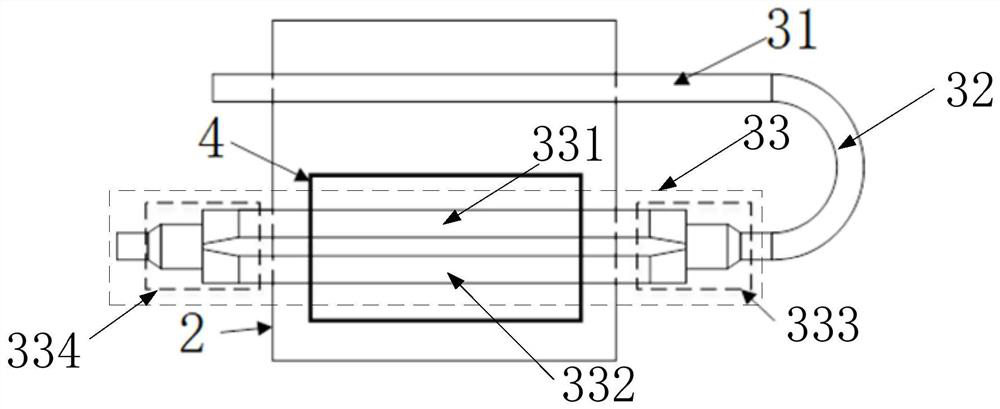
[0048] as mentioned above image 3As shown in , the inflow section 31 is located in other areas outside the main heating area 4 of the frequency conversion module (ie, the heating module 1 in the above embodiment), and the bending section 32 is located in the environment outside the frequency conversion module. The refrigerant driving system drives the refrigerant to enter the inflow section 31 and enter the outflow section through the bending section 32. Through calculation and simulation, it is found that the chips with higher heating power on the frequency conversion module are distributed in the positions ...

Embodiment 3

[0054] This embodiment provides an air conditioner, which includes a heating module, and also includes the refrigerant radiator in the above embodiment, which is used to improve the heat exchange effect, further improve the heat dissipation efficiency, ensure the heat dissipation performance of the heating module, and improve the stability of the device.


PUM


Abstract

The invention discloses a refrigerant radiator, an assembly design method and air conditioning equipment. The refrigerant radiator comprises a cold plate, wherein the cold plate is arranged in a mode of being stacked with a heating module, and a groove is formed in the surface of the side, which is away from the heating module, of the cold plate and used for containing a refrigerant pipe; the cold plate is used for soaking the heat emitted by the heating module; and the refrigerant pipe is embedded into the groove of the cold plate and comprises an inflow section, a bent section and an outflow section, and the outflow section corresponds to a main heating area of the heating module in position and exchanges heat with the main heating area. According to the invention, the heat conduction path of the main heating area and the refrigerant pipe can be shortest, the heat exchange effect is improved, and the heat dissipation efficiency is further improved.

Description

technical field [0001] The invention relates to the technical field of air conditioning, in particular to a refrigerant radiator, an assembly design method and air conditioning equipment. Background technique [0002] The electric control board in the air conditioner usually integrates various circuit modules (such as the frequency conversion module of the electric control board), which will generate a large amount of heat during the operation of the chip and become a heating module. The main heating area of ​​the heating module has a relatively high heating power density. Large, usually need to take separate heat dissipation measures. In related technologies, fans, heat sinks, etc. are used to dissipate heat, and refrigerant cooling is also used to dissipate heat. Compared with the previous two types, refrigerant heat dissipation can greatly reduce the temperature of the variable heating module, so it has become the mainstream heat dissipation technology. However, the cur...

Claims


Application Information

Patent Timeline
Patent Type & Authority Applications(China)
IPC IPC(8): H05K7/20F24F13/00
CPCF24F13/00H05K7/20218H05K7/2039
Inventor 李成林周壮广吴超徐金辉
Owner GREE ELECTRIC APPLIANCES INC
Why Eureka
Try Eureka