Steel structure roof distributed photovoltaic power station photovoltaic module ice and snow removing system and method

A technology of distributed photovoltaics and photovoltaic modules, which is applied in the monitoring of photovoltaic systems, photovoltaic power generation, and integration of power network operating systems. Reliability, improvement of energy utilization rate, effect of small renovation works

Pending Publication Date: 2021-12-28
CEEC HUNAN ELECTRIC POWER DESIGN INST
View PDF5 Cites 0 Cited by
  • Summary
  • Abstract
  • Description
  • Claims
  • Application Information

AI Technical Summary

Problems solved by technology

[0005] At present, the method of distributed photovoltaic power stations with steel structure roofs after snow or freezing weather is manual snow removal or deicing. This method requires a large investment in labor costs, and at the same time, manual snow removal or deicing poses a greater safety risk.
According to the analysis of the prior art, there are mainly the following disadvantages in snow removal or ice melting of photovoltaic modules: (1) The existing technologies CN106788195A, CN203085567U, CN203260591U, and CN206452355U all add energy storage devices to the system, and large-scale energy storage devices are uneconomical. The amount of engineering is large, and it is difficult to realize; (2) the bidirectional inverter scheme adopted by the prior art CN204156540U will increase the number of times the original power electronic devices of the inverter work, and affect the service life of the inverter. It can only be realized in the project, and cannot be used to transform existing projects; (3) The existing technology is to charge the original photovoltaic modules, causing the photovoltaic modules to generate heat, and the cells in the photovoltaic modules are encapsulated in the middle layer. Loss; (4) The existing technology does not properly set the start time of snow removal or ice melting, and the degree of intelligence of the system is low. Randomly starting snow removal or ice melting devices will inevitably cause energy waste

Method used


Image

  • Steel structure roof distributed photovoltaic power station photovoltaic module ice and snow removing system and method
  • Steel structure roof distributed photovoltaic power station photovoltaic module ice and snow removing system and method
  • Steel structure roof distributed photovoltaic power station photovoltaic module ice and snow removing system and method

Examples


Embodiment

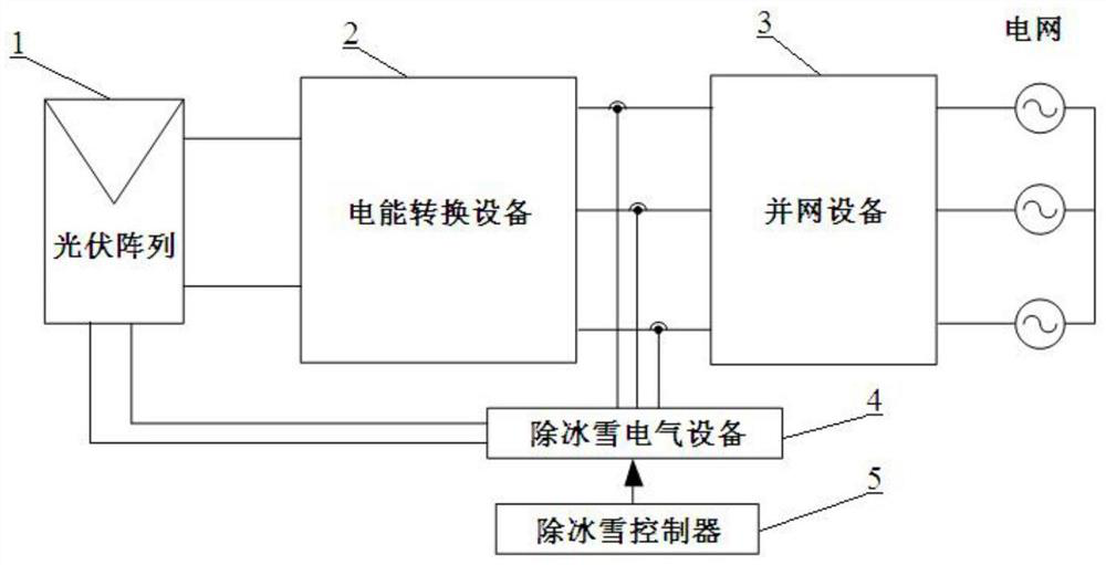
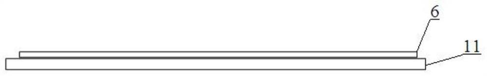
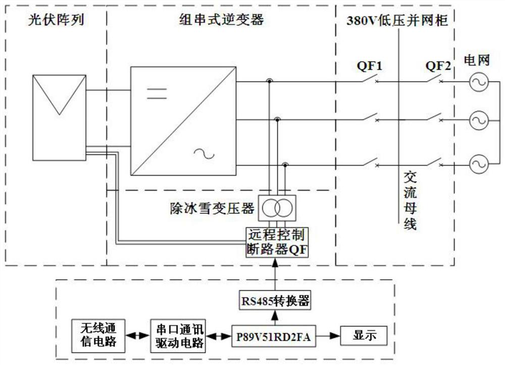
[0047] see Figure 1 to Figure 5 , a system for deicing and snowing photovoltaic modules of a distributed photovoltaic power station with a steel structure roof. The photovoltaic power station includes a photovoltaic array 1, power conversion equipment 2, and grid-connected equipment 3. The deicing and snowing system includes electrical equipment 4 for deicing and snowing, pressure sensors, and a controller for deicing and snowing. 5 and a conductive heating film 6, the photovoltaic array 1 includes a plurality of photovoltaic strings, the number of each photovoltaic string is unique, and the photovoltaic string is formed by a plurality of photovoltaic modules 11 connected in series, and each photovoltaic module 11 A layer of conductive heating film 6 is laid on the upper surface, and the heat dissipated after the conductive heating film is turned on to realize snow removal and ice melting of corresponding photovoltaic modules.

[0048] The power output end of the photovoltaic...


PUM


Abstract

The invention discloses a steel structure roof distributed photovoltaic power station photovoltaic module ice and snow removing system and method. A photovoltaic power station comprises a photovoltaic array, an electric energy conversion device and a grid-connected device, and the ice and snow removing system comprises an ice and snow removing transformer, a circuit breaker and an ice and snow removing controller; conductive heating films are arranged on photovoltaic assemblies of the photovoltaic array, the direct current input end of the electric energy conversion device is connected with the photovoltaic array, the alternating current output end of the electric energy conversion device is connected with a power grid through the grid-connected device, and the wire inlet end of the ice and snow removing transformer is connected with the alternating current output end of the electric energy conversion device or the input end of the grid-connected device. The wire outlet end is connected with the wire inlet end of the circuit breaker, the wire outlet end of the circuit breaker is connected with the conductive heating film, and the ice and snow removing controller is in communication connection with the circuit breaker. The construction amount is small, the system is suitable for different photovoltaic power station schemes, the proper ice and snow removing time point is determined by comparing whether the current roof bearing capacity and energy consumption meet the requirements or not, accurate snow removing and ice melting are achieved, and the energy utilization rate is increased.

Description

technical field [0001] The invention relates to the field of new energy technologies, in particular to a system and method for deicing and snowing photovoltaic modules of a steel structure roof distributed photovoltaic power station. Background technique [0002] Electric energy is the product and main symbol of the second industrial revolution, and it is also an indispensable form of energy utilization for human development. The DC generator was first invented, and the AC generator was invented later. Due to equipment manufacturing technology and the need for long-distance transmission of electric energy, AC has become the mainstream form of power generation. Traditional alternating current is mainly generated by alternators, such as water turbines, steam turbines, diesel engines, etc. Based on these alternator sets, hydropower plants, thermal power plants, nuclear power plants, etc. have been built. Among them, thermal power plants have the advantages of flexible construct...

Claims


Application Information

Patent Timeline
IPC IPC(8): H02S40/12H02J3/38H02S50/00H02J13/00
CPCH02S40/12H02J3/381H02S50/00H02J13/00022H02J13/00016H02J2213/10Y02E10/50Y02E40/70Y02B10/10Y02B70/30Y02B90/20Y04S10/12Y04S10/123Y04S20/242Y04S40/126Y04S40/124
Inventor 刘思佳王国清封焯文赵志华李云涛肖力元朱金峰童威
Owner CEEC HUNAN ELECTRIC POWER DESIGN INST
Why Eureka
Try Eureka