Heat supply system capable of switching from extraction condensing to zero output of low-pressure cylinder and working method of heat supply system

A technology of heating system and working method, which is applied in steam engine installations, machines/engines, mechanical equipment, etc., can solve the problem of rigidity, poor flexibility, poor controllability of large-diameter heating butterfly valves, and heat extraction and steam regulation during the removal of low-pressure cylinders. The narrowing of the scope and other problems, to achieve the effect of flexible heating adjustment capacity, widening the adjustment scope, and simple implementation conditions

Active Publication Date: 2022-05-13
HANGZHOU HUADIAN ENERGY ENG +1
View PDF8 Cites 2 Cited by
  • Summary
  • Abstract
  • Description
  • Claims
  • Application Information

AI Technical Summary

Problems solved by technology

Therefore, mainly due to the poor controllability of the large-diameter heating butterfly valve, the adjustment range of heating and extraction is narrowed.
[0004] During the process of the heating unit from condensate pumping operation to the removal of the low-pressure cylinder, it is difficult to grasp the cut-off time point under different unit load conditions. A certain opening value of the heating butterfly valve in the connecting pipe is often used as the cut-off time point of the low-pressure cylinder, resulting in low pressure Cylinder removal process is too rigid, poor flexibility

Method used


Image

  • Heat supply system capable of switching from extraction condensing to zero output of low-pressure cylinder and working method of heat supply system
  • Heat supply system capable of switching from extraction condensing to zero output of low-pressure cylinder and working method of heat supply system

Examples


Embodiment Construction

[0024] The present invention will be further described in detail below in conjunction with the accompanying drawings and examples. The following examples are explanations of the present invention and the present invention is not limited to the following examples.

[0025] Example.

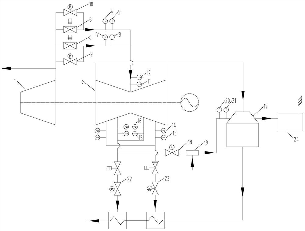
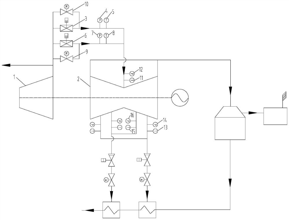
[0026] see Figure 1 to Figure 2 , in this embodiment, a heating system that switches from condensate extraction to low-pressure cylinder zero output, on the basis of the original condensate extraction heating system, a small-diameter communication pipe is added between the medium-pressure cylinder 1 and the low-pressure cylinder 2 , the small-diameter connecting pipeline is installed with a small-diameter heating control valve 3, a pressure sensor 4 and a temperature sensor 5 in sequence, the small-diameter heating control valve 3 is connected in parallel with the original heating butterfly valve 6, and the original heating butterfly valve 6 A pressure sensor 2 7 and a temperature sensor 2 8 are ...


PUM


Abstract

The invention discloses a heat supply system capable of switching from extraction condensing to low-pressure cylinder zero output and a working method of the heat supply system. A small-caliber medium-low pressure communicating pipe with a valve with an adjusting function is additionally arranged on a medium-low pressure communicating pipe of an original heat supply extraction condensing unit in parallel and serves as low-pressure cylinder steam inlet flow control before the low-pressure cylinder is cut off; temperature and pressure sensor monitoring data are newly added on an original seven-section steam extraction pipeline of the low-pressure cylinder to be connected into a unit control system, and the steam superheat degree is obtained and serves as a criterion of a low-pressure cylinder removal time point; a pipeline with a valve is additionally arranged in a pipeline between a six-section steam extraction valve of a low-pressure cylinder and the low-pressure cylinder to a condenser, when the cutting-off time point of the low-pressure cylinder arrives, the six-section steam extraction valve and the seven-section steam extraction valve are closed firstly, then a small-caliber medium-low pressure communicating pipe valve is closed, and finally the valve between the six-section steam extraction valve and the condenser is opened. Non-condensed gas in the low-pressure cylinder and hot standby steam of the communicating pipe are pumped out in advance, and the system ensures normal operation of the long movable blade of the low-pressure cylinder in a high-vacuum environment and no overtemperature of the inlet of the condenser.

Description

technical field [0001] The invention belongs to the technical field of combined heat and power generation and steam turbine operation, and specifically relates to a heating system and a working method thereof that switch from condensate extraction to low-pressure cylinder zero output. Background technique [0002] At present, in order to improve the heating and peak-shaving capacity of the heating units, the heating units in the northern region are implementing the "low-pressure cylinder zero output" transformation, that is, the steam turbine operates without the low-pressure cylinder during the heating peak-shaving period. The mainstream method is to add a small-flow steam pipeline between the medium and low-pressure cylinders to cool the blast heat in the low-pressure cylinder. The cylinder is sprayed with water for cooling. In the actual application of this method, the steam with a small flow rate does not play a cooling role, but only accelerates the flow to take away t...

Claims


Application Information

Patent Timeline
Patent Type & Authority Applications(China)
IPC IPC(8): F01K17/02F01K11/02F01K7/02F01K7/16F01K7/38F01K13/00
CPCF01K17/02F01K11/02F01K7/02F01K7/16F01K7/38F01K13/00
Inventor 王启业王丰吉郑立军俞聪王伟
Owner HANGZHOU HUADIAN ENERGY ENG
Why Eureka
Try Eureka