Ammonia spraying pipeline and denitration ammonia spraying device

A pipeline and nozzle technology, applied in the field of denitrification and ammonia injection devices, can solve the problems of large proportion of flue cross-sectional area, etc., and achieve the effects of improving energy saving effect, effect guarantee, and reducing wear degree

Pending Publication Date: 2021-06-11
CHINA HUADIAN ENG +1
View PDF0 Cites 3 Cited by
  • Summary
  • Abstract
  • Description
  • Claims
  • Application Information

AI Technical Summary

Problems solved by technology

[0004] Therefore, the technical problem to be solved by the present invention is to overcome the defect in the prior art that the projected area of ​​the ammonia injection pipe occupies a relatively large proportion of the cross-sectional area of ​​the flue in the flue, thereby providing a method to reduce the flow rate of the ammonia injection while ensuring that the flow rate of the ammonia injection remains unchanged. The ratio of the projected area of ​​the small pipe in the flue to the ammonia injection pipe

Method used


Image

  • Ammonia spraying pipeline and denitration ammonia spraying device
  • Ammonia spraying pipeline and denitration ammonia spraying device
  • Ammonia spraying pipeline and denitration ammonia spraying device

Examples


Embodiment 1

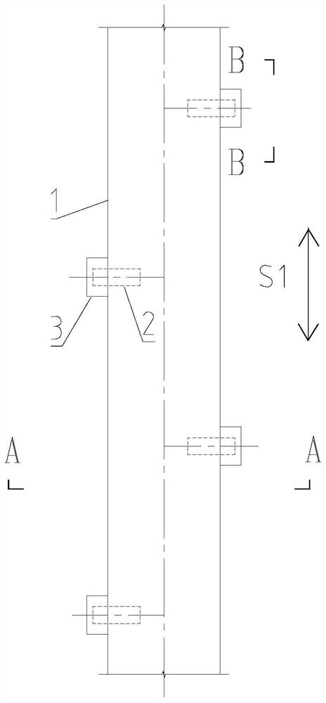
[0041] combine Figure 1-Figure 3 As shown, the ammonia injection pipeline provided by the present embodiment includes:

[0042] Ammonia injection pipe body 1;

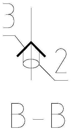
[0043] The nozzle 2 is arranged on the ammonia injection pipeline body 1 and communicates with the inside of the ammonia injection pipeline body 1; and

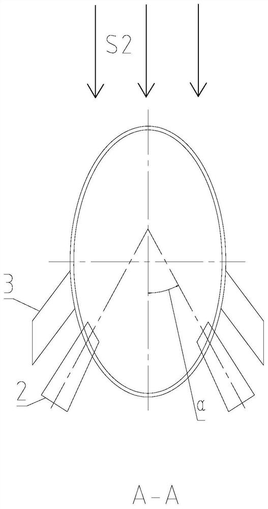
[0044] The protective angle steel 3 is arranged on the outer surface of the ammonia injection pipe body 1, and is arranged at the position near the wind end of the flue gas flow direction S2 relative to the nozzle 2, and is suitable for at least partially covering the nozzle 2;

[0045]The cross-section of the ammonia injection pipeline body 1 perpendicular to the ammonia delivery direction S1 is an elliptical structure; and the long axis of the elliptical structure is arranged parallel to the flue gas flow direction S2.

[0046] In the ammonia injection pipeline provided in this embodiment, the cross section of the ammonia injection pipeline body 1 perpendicular t...

Embodiment 2

[0069] combine figure 1 As shown, this embodiment provides a denitrification ammonia injection device, including: the ammonia injection pipeline as described in the first embodiment above, and the ammonia injection pipeline is arranged in the flue.

[0070] The traditional circular cross-section ammonia injection pipes are arranged side by side and parallel inside the flue. The projected area of ​​the pipes occupies almost 20% of the entire cross-sectional area of ​​the flue. The effective cross-section through which the flue gas can pass is reduced, which greatly increases the resistance and energy consumption.

[0071] The denitrification ammonia injection device provided in this embodiment adopts an elliptical ammonia injection pipeline and the long axis of the elliptical structure is arranged parallel to the flue gas flow direction S2, thereby replacing the traditional circular section. In the case of completely equal cross-sectional areas, The ammonia injection flow rate...


PUM


Abstract

The invention relates to the technical field of denitration ammonia spraying devices, in particular to an ammonia spraying pipeline and a denitration ammonia spraying device. The ammonia spraying pipeline comprises an ammonia spraying pipeline body, a nozzle and protective angle steel, wherein the nozzle is arranged on the ammonia spraying pipeline body and is communicated with the interior of the ammonia spraying pipeline body; the protective angle steel is arranged on the outer surface of the ammonia spraying pipeline body, is arranged at a near-wind end of thethe flue gas flow direction S2relative to the nozzle, and is suitable for at least partially covering the nozzle; the section, which is perpendicular to the ammonia gas conveying direction S1, of the ammonia spraying pipeline body is of an oval structure; and the long axis of the oval structure is parallel to the flue gas flow direction S2. According to the ammonia spraying pipeline provided by the invention, the wind shielding area of the ammonia spraying pipeline can be reduced, the resistance of a system is reduced, the efficiency of the system is improved, and accurate energy conservation is realized.

Description

technical field [0001] The invention relates to the technical field of denitrification ammonia injection devices, in particular to an ammonia injection pipeline and a denitrification ammonia injection device. Background technique [0002] Flue gas from thermal power plants contains a large amount of nitrogen oxides. If these exhaust gases are not treated, they will cause pollution and form acid rain when they are discharged into the atmosphere. In order to reduce the emission of nitrogen oxides, it is necessary to denitrify the flue gas after combustion. In the prior art, thermal power plants often need to use flue gas denitrification devices. Many ammonia injection devices are installed in the vertical section of the denitrification reactor for the injection of ammonia gas. Ammonia gas is used as a reducing agent. Nitrogen oxides are released from the reaction in the vessel. The existing ammonia injection device is made of circular steel pipes, holes are opened on the circ...

Claims


Application Information

Patent Timeline
IPC IPC(8): B01D53/76B01D53/56
CPCB01D53/56B01D53/76B01D2251/2062B01D2258/0283
Inventor 夏怀鹏白永锋吴冲王凯亮汪洋李伟
Owner CHINA HUADIAN ENG
Why Eureka
Try Eureka