Automatic chip removing device for numerical control lathe
A numerical control lathe and automatic row technology, which is applied in the field of numerical control lathes to achieve the effect of reducing the splash of iron filings
- Summary
- Abstract
- Description
- Claims
- Application Information
AI Technical Summary
Problems solved by technology
Method used
Image
Examples
Embodiment 1
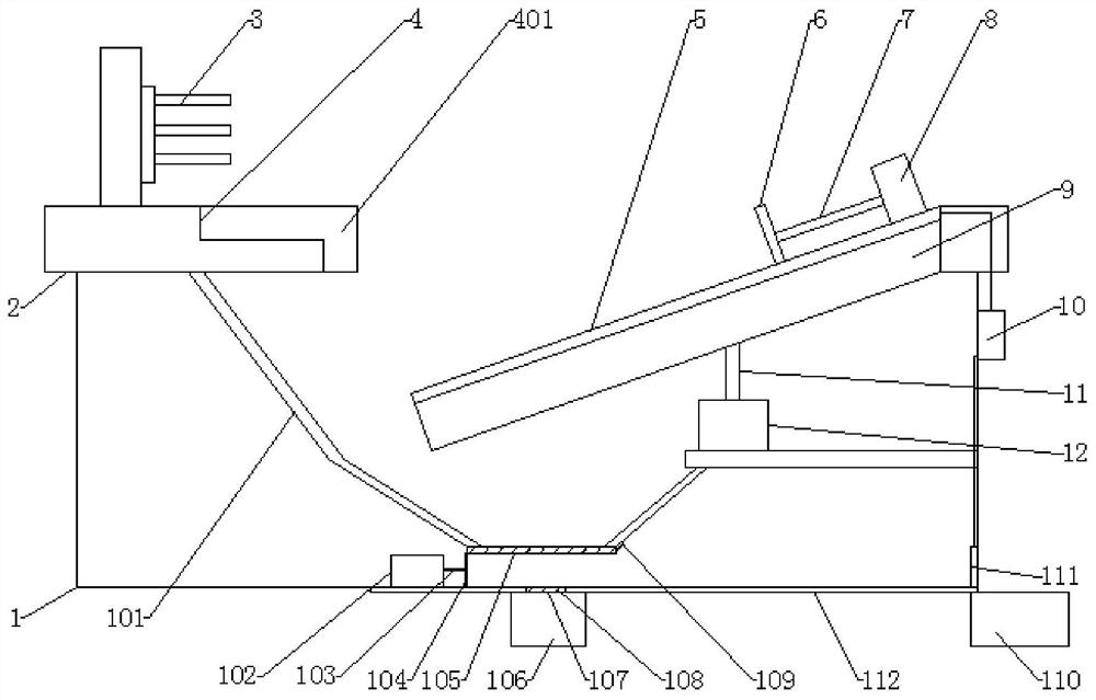
[0024] See attached Figure 1-2 , an automatic chip removal device for a numerically controlled lathe, comprising a lathe main body 1 and a workbench 2 arranged on the lathe main body 1, a cleaning module 4 is arranged on the lathe main body, and the cleaning module 4 is installed on the claw 3 Below, the cleaning module 4 is used to receive the cutting chips generated by the machine tool, and separate the cutting fluid in the cutting chips;
[0025] The cleaning module 4 includes a drainage groove 401, a baffle plate 101, a first filter screen 105, and a second scraper 104. The drainage groove 401 is opened on the workbench 2, and the baffle plate 101 is arranged on the drainage groove 401. The two sides below form a sealed space with the drainage groove 401, the first filter screen 105 is arranged at the bottom of the sealed space, the second scraper 104 is arranged at the bottom of the lathe main body 1, and the second scraper The top of the plate 104 is in contact with th...
Embodiment 2
[0032] On the basis of Example 1, the automatic chip removal device for CNC lathe in Example 1 is further optimized:
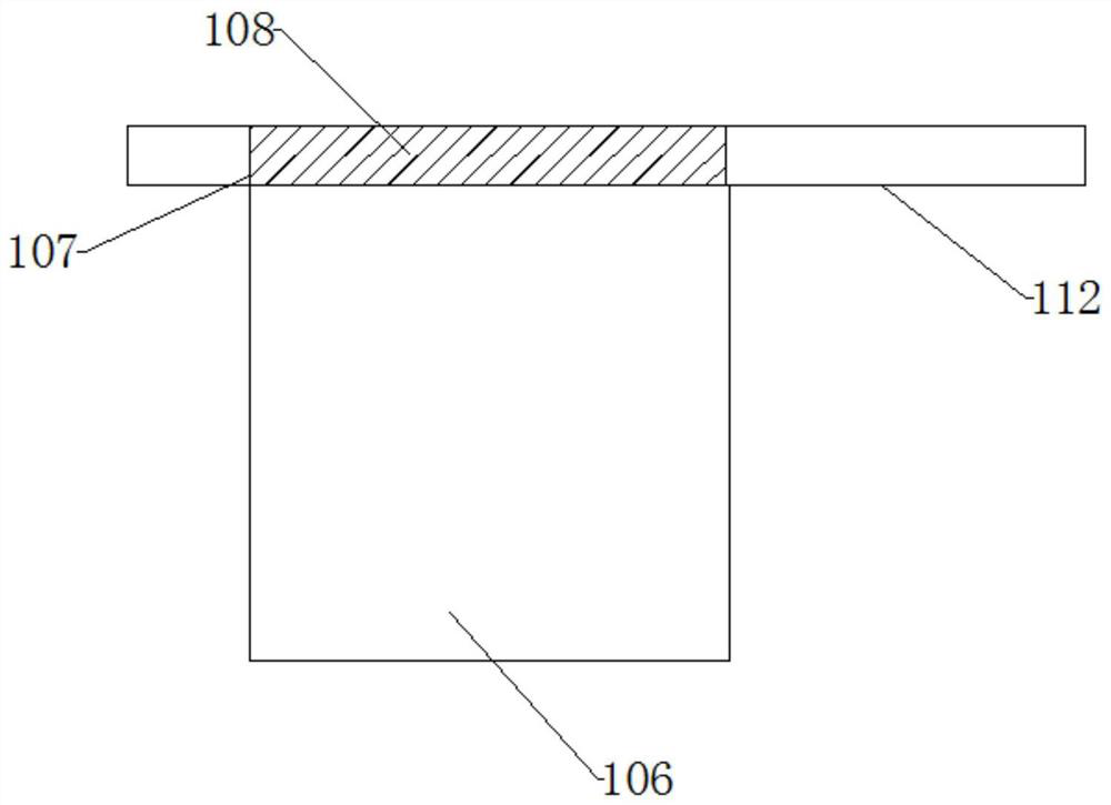
[0033] The bottom of the lathe body 1 is provided with a backing plate 112 , and the bottom of the backing plate 112 is provided with a cutting fluid recovery tank 106 , and the backing plate 112 is provided with a permeable hole 107 .
[0034] Specifically, the cutting fluid flows out from the first filter screen 105 and enters the semi-closed space formed by the lathe body 1, the push plate, and the backing plate 112, and the third pushing hydraulic cylinder 102 pushes The second scraper 104 moves so that the cutting fluid entering the semi-enclosed space flows out through the permeable hole 107 .
[0035] Preferably, the water permeable hole 107 is provided with a second filter screen 108, the height of the second filter screen 108 does not exceed the height of the water permeable hole 107, and the second filter screen 108 is covered above the water permeab...
Embodiment 3
[0037] On the basis of Example 1, the automatic chip removal device for CNC lathe in Example 1 is further optimized:
[0038] An iron filings recovery box 110 is provided on the side of the backing plate 112 close to the power source 10 .
[0039] Specifically, the scrap iron recovery box 110 recovers the separated scrap iron.
[0040] Preferably, an electric door 111 is provided at the bottom of the lathe main body 1 close to the iron filings recovery box 110, the electric door 111 is electrically connected to the power supply 10, and the power supply 10 provides power for the electric door 111, After the electric door 111 is opened, the second scraper 104 pushes out the iron filings entering the semi-enclosed space, so that the iron filings enter the iron filings recovery box 110 of the type crusher.
[0041] In the specific use process, the parts to be processed are placed in the jaws 3 for fixing, the lathe main body 1 starts to work, and the parts to be processed are cut...
PUM
 Abstract
Description
Claims
Application Information
 - R&D
- Intellectual Property
- Life Sciences
- Materials
- Tech Scout
- Unparalleled Data Quality
- Higher Quality Content
- 60% Fewer Hallucinations
Browse by: Latest US Patents, China's latest patents, Technical Efficacy Thesaurus, Application Domain, Technology Topic, Popular Technical Reports.
© 2025 PatSnap. All rights reserved.Legal|Privacy policy|Modern Slavery Act Transparency Statement|Sitemap|About US| Contact US: help@patsnap.com


