Injection mechanism of injection molding machine

An injection molding machine and glue injection technology, which is applied in the field of injection mechanism of injection molding machines, can solve problems such as poor quality of finished products

Inactive Publication Date: 2021-06-11
周立銮
View PDF0 Cites 1 Cited by
  • Summary
  • Abstract
  • Description
  • Claims
  • Application Information

AI Technical Summary

Problems solved by technology

[0003] In view of the deficiencies in the prior art, the object of the present invention is to provide a glue injection mechanism of an injection molding machine, so that when the polycarbonate in the molten state is pushed, the polycarbonate will stick to the surface of the screw, and when it is used next time, The polycarbonate sticking to the surface of the screw will be partially dissolved due to the temperature carried by the new polycarbonate, and then mixed with the new polycarbonate and injected into the mold together, resulting in poor quality of the finished product

Method used


Image

  • Injection mechanism of injection molding machine
  • Injection mechanism of injection molding machine
  • Injection mechanism of injection molding machine

Examples


Embodiment 1

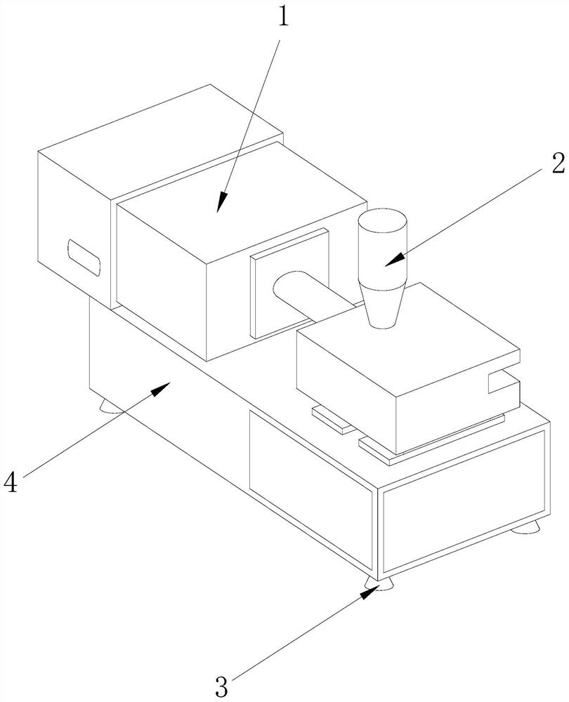
[0023] as attached figure 1 To attach Figure 5 Shown:

[0024] The invention provides a glue injection mechanism of an injection molding machine, the structure of which includes: a body 1, a feed port 2, a support leg 3, and a base 4, the bottom surface of the body 1 is welded to the top surface of the base 4, and the inlet The feed port 2 is nested above the fuselage 1, and the top surface of the support foot 3 is welded to the bottom surface of the base 4,

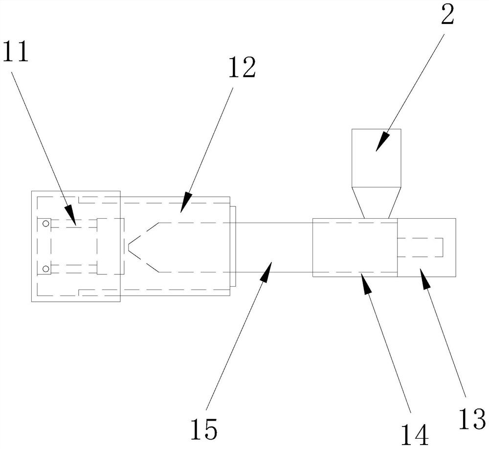
[0025] The fuselage 1 includes a positioning frame 11, a casing 12, a driver 13, a heater 14, and a barrel 15. The left side of the positioning frame 11 is bolted to the inside of the casing 12, and the inner ring of the driver 13 is connected to the machine barrel. The outer ring on the right side of the barrel 15 is embedded and connected, the heater 14 surrounds the outer ring of the barrel 15 , and the outer ring on the left side of the barrel 15 is embedded and connected to the inner side of the casing 12 .

[...

Embodiment 2

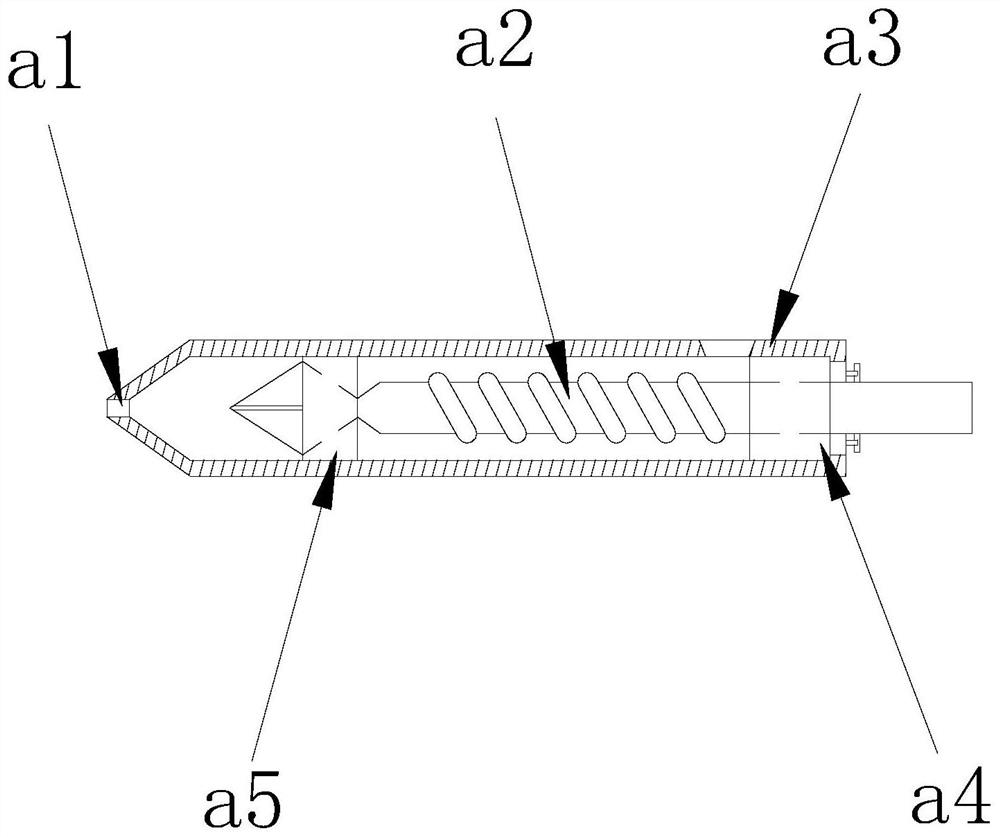
[0032] as attached Figure 5 As shown: the scraping device b1 includes a limiting ring c1, a circular ring c2, a scraping plate c3, an elastic spring c4, and a collecting device c5. The limiting ring c1 and the circular ring c2 are an integrated structure, and the scraping One side of the removal plate c3 is bolted to one side of the elastic spring c3, ​​one side of the elastic spring c4 is nested inside the limit ring c1, the collecting device c5 is welded below the ring c2, the The scraper plate c3 is annularly distributed on the outside of the screw a2, so the scraper plate c3 can scrape off the residual material on the surface of the screw a2.

[0033] as attached Image 6 To attach Figure 7 Shown:

[0034] The present invention provides a glue injection mechanism of an injection molding machine. The collection device c5 includes a baffle d1, a collection box d2, an adsorption device d3, and a round hole d4. The baffle d1 is welded to the upper rear of the collection b...


PUM


Abstract

The invention provides an injection mechanism of an injection molding machine. The injection mechanism structurally comprises a machine body, a feeding port, supporting legs and a base, the bottom surface of the machine body is welded to the top surface of the base, the feeding port is embedded in the upper portion of the machine body, and the top surfaces of the supporting legs are welded to the bottom surface of the base. According to the injection mechanism of the injection molding machine, when injection molding is carried out on polycarbonate materials, the materials are poured into a machine barrel through the feeding port, so that a driver is started, a heater melts the materials, then pushing is carried out on the materials in the molten state, heat is generated in the heating process, mercury expands when encountering heat, a scraping plate moves under the action of the mercury in the process that a screw rod pushes the materials, when the use is finished, the mercury contracts to drive the scraping plate to restore to the original shape, and therefore scraping is carried out on the screw rod, the phenomenon that residual materials on the surface of the screw rod are fused with new materials in the next use process can be avoided, and the scraped materials enter a collecting box through a round hole, so that the materials are adsorbed to an adsorption device.

Description

technical field [0001] The invention relates to the field of plastic injection, in particular to a plastic injection mechanism of an injection molding machine. Background technique [0002] The injection molding machine puts a certain amount of material inside the equipment for heating within a specified time, and then uses the thrust of the screw or plunger to inject the plasticized molten material into the closed cavity through the injection mechanism. Inside, after the injection is finished, the finished product can be obtained after a period of fixed setting, but the injection mechanism of the injection molding machine in the prior art, when injecting polycarbonate materials, due to the high viscosity of polycarbonate, it is easy to decompose. As a result, when the screw pushes the polycarbonate in the molten state, the polycarbonate will stick to the surface of the screw, and when it is used next time, the polycarbonate sticking to the surface of the screw will die due ...

Claims


Application Information

Patent Timeline
IPC IPC(8): B29C45/03B29C45/17B29C45/18B29C45/47B29C45/58B29C45/74
CPCB29C45/03B29C45/1753B29C45/18B29C45/47B29C45/58B29C45/74
Inventor 周立銮
Owner 周立銮
Why Eureka
Try Eureka