Winding device for non-woven fabric production

A winding device and non-woven fabric technology, which is applied in the direction of winding strips, transportation and packaging, thin material processing, etc., can solve the problems of high labor intensity for workers, low efficiency of replacing winding rollers, low winding efficiency, etc. , to achieve the effect of shortening the processing time, ensuring the quality of the field products, and improving the winding efficiency

Inactive Publication Date: 2021-06-11
厦门谷岩纺织有限公司
View PDF1 Cites 2 Cited by
  • Summary
  • Abstract
  • Description
  • Claims
  • Application Information

AI Technical Summary

Problems solved by technology

[0007] Aiming at the deficiencies of the prior art, the present invention provides a winding device for the production of non-woven fabrics, which overcomes the deficiencies of the prior art, has a reasonable design and a compact structure, and aims to solve the problem of the efficiency of replacing the receiving roller after the non-woven fabric is wound. Low, high labor intensity of the staff, the replacement of the take-up roller needs to be shut down, which leads to the problem of low winding efficiency

Method used


Image

  • Winding device for non-woven fabric production
  • Winding device for non-woven fabric production
  • Winding device for non-woven fabric production

Examples


Embodiment 1

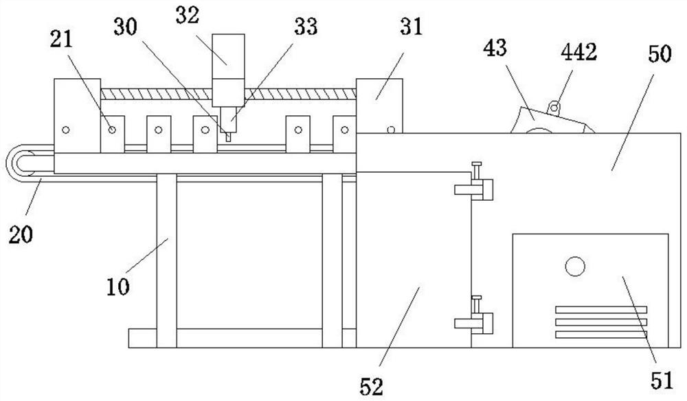
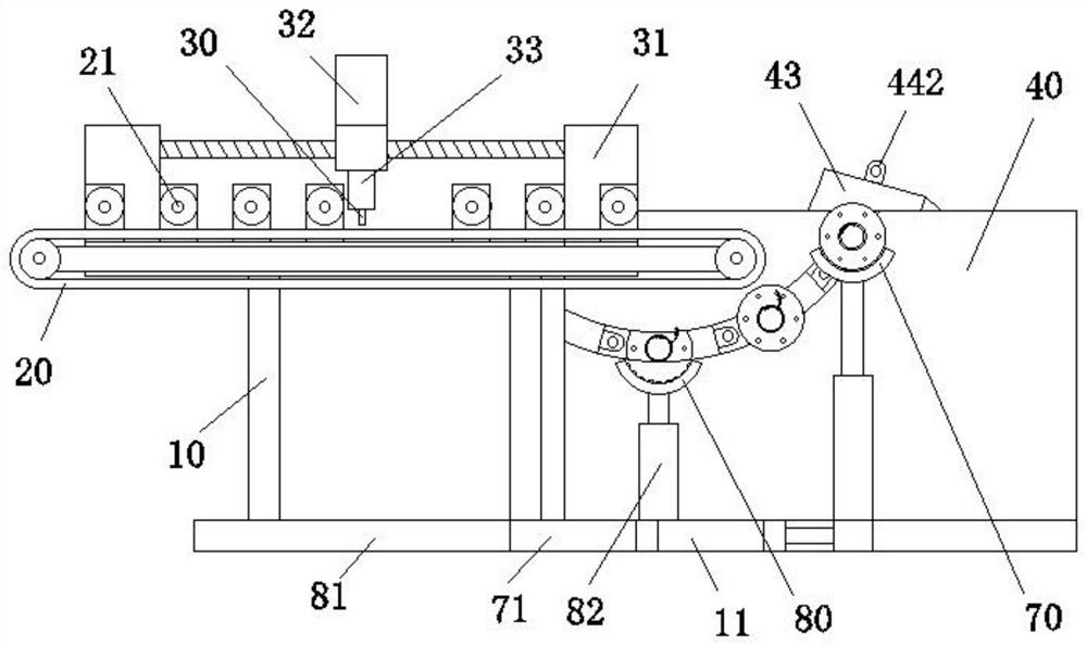
[0037] refer to Figure 1-6, a winding device for non-woven fabric production, comprising a truss 10, a conveyor belt 20 mounted on the truss 10, a cutter 30 positioned at the top of the conveyor belt 20, a lifting platform 70 located obliquely below the conveyor belt 20, the two sides of the lifting platform 70 are connected The components are identical and arranged symmetrically; the side of the truss 10 away from the lift platform 70 is fixed with a side plate 40, and the side wall of the side plate 40 close to the truss 10 is provided with a storage slot 41 with an arc-shaped vertical section, and an opening at one end of the storage slot 41 Located at the top of the side plate 40, the other end opening of the storage tank 41 is located on the side wall of the side plate 40, and the other end opening of the storage tank 41 is located on the side wall of the side plate 40, and the storage tank 41 is slidingly connected to three structures with the same structure. And the sl...

Embodiment 2

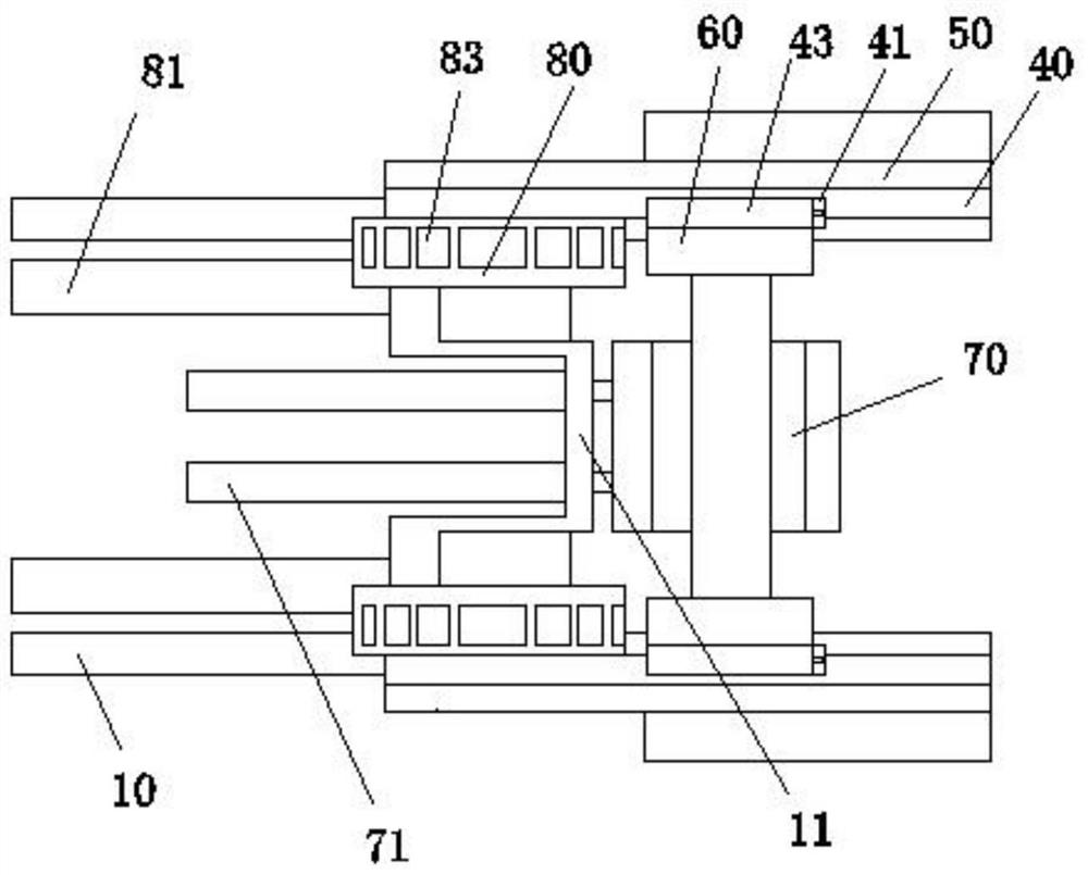
[0044] refer to Figure 1-6 , a winding device for non-woven fabric production, the same as Embodiment 1, the difference between this embodiment and Embodiment 1 is that the bottom of the side wall of the truss 10 is fixed with a horizontally arranged mounting plate 11, and the top of the mounting plate 11 is horizontal. The cross-section is a few-shaped structure, and the middle part of one side of the mounting plate 11 is fixed with two hydraulic cylinders 71 arranged horizontally. Both are provided with a hydraulic cylinder 2 81 fixed on the end of the mounting plate 11, the output end of the hydraulic cylinder 2 81 is fixed with a base plate, and the top of the base plate is fixed with a loading platform 80 through a vertical hydraulic cylinder 3 82, and the loading platform 80 Located below the end of the conveyor belt 20.

[0045] Working principle: the hydraulic cylinder 1 71 works to move the lifting platform 70 in the horizontal direction, and the lifting platform 70...

Embodiment 3

[0048] refer to Figure 1-6 , a winding device for the production of non-woven fabrics, the same as the second embodiment, the difference between this embodiment and the second embodiment is that a connecting groove 441 is provided on the vertical side wall of the slide plate 43, and the other vertical wall of the slide plate 43 A connecting plate 442 is arranged on one side wall, and two adjacent slide plates 43 are fixed by connecting grooves 441 and connecting plates 442. The side wall of the slide plate 43 is provided with a convex tooth 45, the convex tooth 45 meshes with the gear 42, and the drive wheel 433 and the turntable 432 are one of meshing connection and belt connection. 43 interiors are embedded with a storage battery that drives the drive wheel 433 to rotate, and the side wall of the drive wheel 433 is provided with a pin hole 46, and the drive wheel 433 is pinned to the receiving roller 60 by a fixed pin, which is convenient for the disassembly and assembly of...


PUM


Abstract

The invention relates to the field of non-woven fabric production, discloses a winding device for non-woven fabric production. The device aims to solve the problems that after non-woven fabric is wound, the efficiency of replacing a material collecting roller is low, the labor intensity of workers is high, and the winding efficiency is low due to the fact that a machine needs to be stopped when the material collecting roller is replaced. The device comprises a truss, a conveying belt installed on the truss, a cutter located at the top of the conveying belt and a lifting table located below the conveying belt, a side plate is fixed to one side, away from the lifting table, of the truss, a storage groove with an arc-shaped vertical section is formed in the side wall, close to the truss, of the side plate, an opening in one end of the storage groove is located in the top of the side plate, three sliding plates which are of the same structure and are sequentially connected are connected into the storage groove in a sliding mode, and a gear for driving the sliding plates to rotate is fixed into the storage groove. The device is simple in structure, reasonable in design and small in occupied space, reduces the probability of defective products after non-woven fabric winding, saves energy, is environmentally friendly, is particularly suitable for non-woven fabric production winding in an unmanned workshop, and has a high application prospect.

Description

technical field [0001] The invention relates to the technical field of non-woven fabric production, in particular to a winding device for non-woven fabric production. Background technique [0002] Non-woven fabric is a kind of non-woven fabric, which directly uses polymer chips, short fibers or filaments to form fibers through airflow or machinery, and then undergoes hydroentanglement, needle punching, or hot rolling reinforcement, and finally undergoes post-treatment Formed non-woven fabric. [0003] In the existing technology, the winding equipment of non-woven fabrics includes a frame, a receiving roller erected on the frame and arranged in a horizontal direction, and a motor that drives the receiving roller to rotate around its axis. When the non-woven fabric After the winding is completed, the rewinding roller needs to be replaced, which is inconvenient to replace, the work intensity of the staff is high, and the replacement efficiency is low. [0004] The patent with...

Claims


Application Information

Patent Timeline
Patent Type & Authority Applications(China)
IPC IPC(8): B65H18/08B65H18/02B65H19/26B65H19/30
CPCB65H18/028B65H18/08B65H19/26B65H19/30B65H2701/19
Inventor 陈明华
Owner 厦门谷岩纺织有限公司
Why Eureka
Try Eureka