Construction method of prestressed immersed tunnel pipe joint

A construction method and technology of immersed tube tunnels, which are applied in construction, water conservancy projects, artificial islands, etc., can solve the problems of inconvenient concrete pouring and vibration, difficulty in adapting to long-span structures, and large burial depth of immersed tube tunnels, etc. Corrosion ability, reduced labor intensity, and low project cost

Inactive Publication Date: 2021-06-11
CHINA RAILWAY TUNNEL SURVEY & DESIGN INST +1
View PDF5 Cites 1 Cited by
  • Summary
  • Abstract
  • Description
  • Claims
  • Application Information

AI Technical Summary

Problems solved by technology

The thickness of the structure is 1.2-1.4m, and it is necessary to configure 2-3 rows of steel bars with a diameter of 32mm and a spacing of 100mm. The steel bars are very dense, and the concrete pouring and vibrating is extremely inconvenient and the construction labor intensity is high.
[0007] 2) The immersed tube tunnel has a large load, a large structural span, and limited structural thickness. Multiple shear stirrups need to be installed at both ends of the tunnel roof and floor. The stirrups are very dense, and the concrete pouring and vibrating is extremely inconvenient and the construction labor intensity is high.
[0008] 3) Due to the deep burial of immersed tube tunnels and incomplete statistics, the steel content of most sections exceeds 250-300kg / m 3 , far exceeding the steel content of 150-180kg / m in ordinary underground engineering 3 , causing huge waste to the project
[0009] 4) It is difficult to adapt to the large-span structure
For example, the Shenzhen-Zhongshan subsea tunnel project has two-way eight-lane lanes, and the crack width calculation of the quasi-permanent load structure of the reinforced concrete section seriously exceeds the specification limit requirements. Currently, steel shell concrete pipe joints are used, which greatly increases the project cost.

Method used


Image

  • Construction method of prestressed immersed tunnel pipe joint

Examples


Embodiment Construction

[0027] In order to enable those skilled in the art to better understand the technical solution of the present invention, the present invention will be described in detail below in conjunction with the accompanying drawings and specific embodiments.

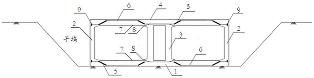
[0028] This embodiment provides a method for constructing pipe joints of prestressed immersed tube tunnels, such as figure 1 As shown, the method includes the following steps:

[0029] Step S1, tying steel bars of the pipe joint bottom plate 1 in the dry dock, laying prestressed tensioned casings and steel strands 7 on the pipe joint bottom plate 1, and pouring concrete for the pipe joint bottom plate 1;

[0030] Step S2, constructing reinforced concrete for pipe section side wall 2 and pipe section middle partition wall 3;

[0031] Step S3, tying the steel bars of the pipe joint top plate 4, laying the prestressed tensioned casing and the steel strand 7 on the pipe joint top plate 4, and pouring the pipe joint top plate 4 concre...


PUM


Abstract

The invention provides a construction method of a prestressed immersed tunnel pipe joint. The construction method comprises the following steps of: binding pipe joint bottom plate steel bars in a dry dock, laying prestressed tensioned sleeves and steel strands, and pouring pipe joint bottom plate concrete; constructing pipe joint side wall and middle partition wall reinforced concrete; binding pipe joint top plate steel bars, laying prestressed tensioned sleeves and steel strands, and pouring top plate concrete; constructing door sealing structures at two ends of the pipe joint; locking the steel strands in anchoring ends on the pipe joint side walls, after the strength of the pipe joint concrete reaches a design value, horizontally tensioning the steel strands of the top plate and the bottom plate at the middle partition wall from the tensioning ends, and after the steel strands reach a tensioning preset value, locking the steel strands; grouting in the embedded sleeves, blocking the sleeves, and blocking anchorage device hand holes; and constructing a pipe joint outer waterproof layer, floating the pipe joint in the dry dock, mounting fitting-out components, and preparing pipe joint floating transportation. The construction method is suitable for reinforced concrete pipe joints with larger spans, and the adaptability of an immersed tunnel is enhanced; and the durability of the pipe joint can be improved, and the total construction cost of the immersed tunnel can be greatly reduced.

Description

technical field [0001] The invention belongs to the technical field of immersed tube tunnel engineering, and in particular relates to a method for constructing pipe joints of prestressed immersed tube tunnels. Background technique [0002] There are many rivers, lakes and seas in my country, and the water system is developed. The inland water area reaches 174,700 square kilometers, the Bohai Bay and other sea areas reach 5,000 square kilometers, and the total length of rivers, lakes and coastlines is 460,000 kilometers. There are 300 cities with a population of over one million in China, 98% of which are built and prospered by rivers. While rivers bring development to cities, they also divide cities, which to a certain extent restricts the country's overall traffic roads. Network formation and rapid urban development. [0003] With the rapid development of my country's economy, the improvement of tunnel construction technology, and the continuous enhancement of the country'...

Claims


Application Information

Patent Timeline
Patent Type & Authority Applications(China)
IPC IPC(8): E02D29/073
CPCE02D29/073E02D2250/0023
Inventor 贺维国周华贵曹威范国刚
Owner CHINA RAILWAY TUNNEL SURVEY & DESIGN INST
Why Eureka
Try Eureka