
Building steel formwork structure

A construction steel and formwork technology, which is applied in the direction of building structure, formwork/formwork components, buildings, etc., can solve the problems of accelerated separation speed, damage of steel formwork and concrete, high density, etc., to increase the bonding tightness, The effect of reducing the difficulty of transportation and reducing the possibility

Active Publication Date: 2021-06-11
浙江隆曦建筑工程有限公司
View PDF15 Cites 2 Cited by
  • Summary
  • Abstract
  • Description
  • Claims
  • Application Information

AI Technical Summary

Problems solved by technology

[0004] (1) The density of steel is high, and the volume of steel formwork is often large, so the overall weight of steel formwork is large, and it needs to be lifted by lifting machinery when it is moved and installed, and the time cost and economic cost invested are relatively high;
[0005] (2) When demolding, the staff needs to use tools to manually tap the steel formwork to speed up the separation of the concrete and the steel formwork. Due to the uncertainty of manual operation, it is difficult to ensure the knocking on the steel formwork everywhere. The force is the same, if the percussion force is too high, it will cause damage to the steel formwork and concrete, and if the percussion force is too small, it will not be able to speed up the separation of the two

Method used


Image

  • Building steel formwork structure
  • Building steel formwork structure
  • Building steel formwork structure

Examples


Embodiment Construction

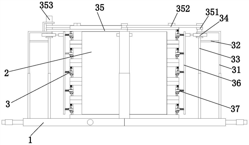
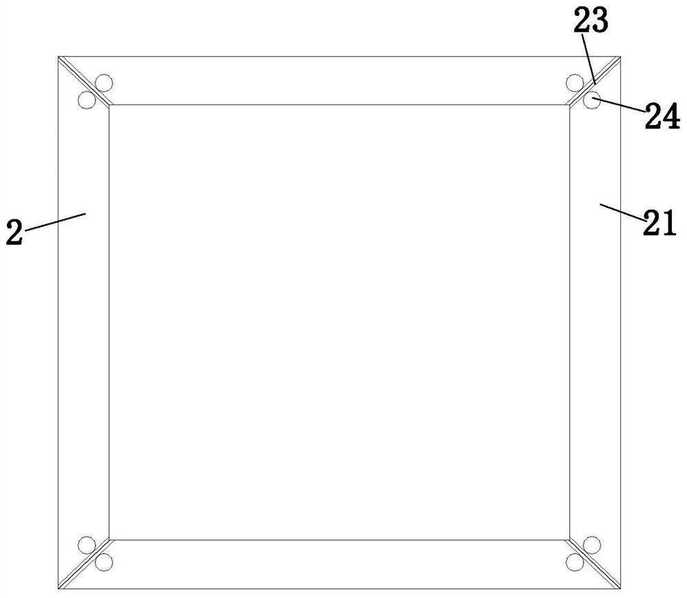
[0029] The embodiments of the present invention will be described in detail below with reference to the accompanying drawings, but the present invention can be implemented in many different ways defined and covered by the claims.

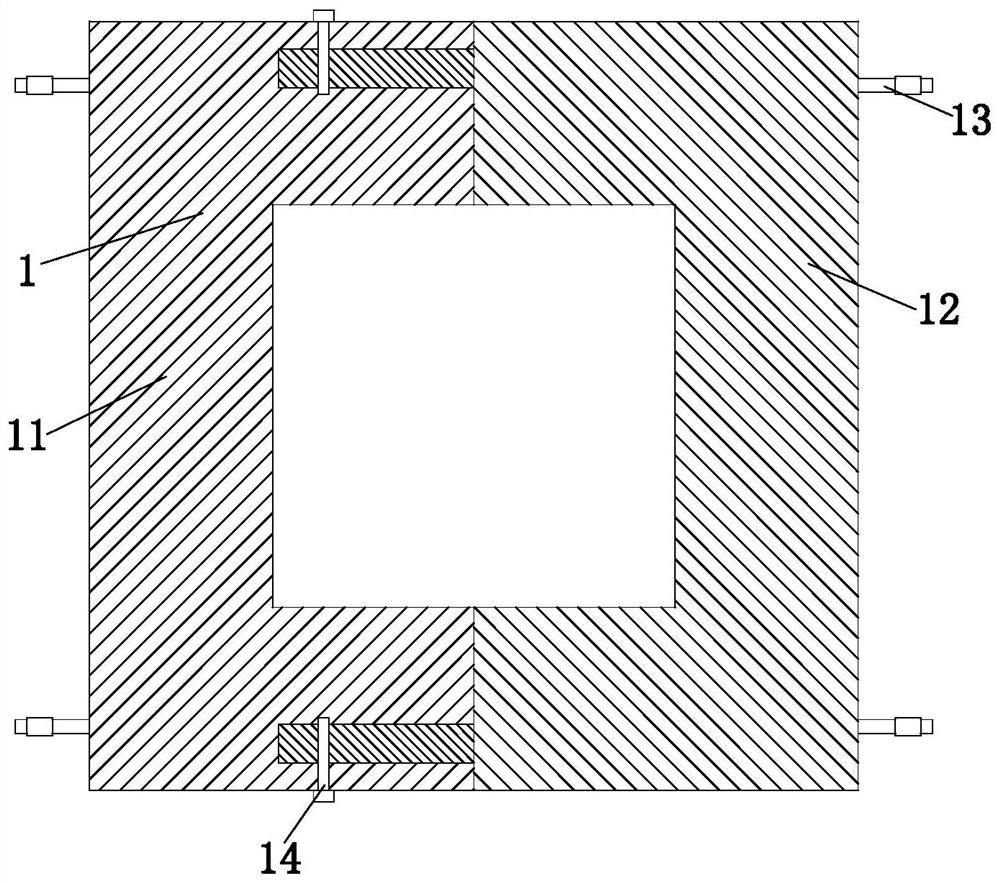
[0030] Such as Figure 1 to Figure 8 As shown, a building steel formwork structure includes a bottom plate 1, a formwork body 2 and a demoulding device 3, the bottom plate 1 is a back-shaped structure, a formwork body 2 is installed on the upper end of the bottom plate 1, and a demoulding device is arranged outside the formwork body 2 3. The demoulding device 3 is installed on the bottom plate 1; wherein:

[0031] Described bottom plate 1 comprises left base plate 11, right base plate 12, handle 13 and connecting bolt 14, and left base plate 11 and right base plate 12 are left and right relative arrangements, and handle 13 is all installed on left base plate 11 and right base plate 12 outer walls, left base plate 11 and The right base plates 12 are...


PUM


Abstract

The invention relates to a building steel formwork structure. The building steel formwork structure comprises a bottom plate, a formwork main body and a demolding device, wherein the demolding device comprises a mounting frame, a connecting plate, a lifting frame, a vibration cam, a transmission mechanism, a vibration plate and a vibration rod, and the formwork main body comprises a plurality of side plates, sealing pieces, rubber gaskets and connecting rods which are arranged from top to bottom. According to the building steel formwork structure, both the formwork main body and the bottom plate are of a detachable structure, the formwork main body can be separately conveyed in a transferring process, compared with an overall conveying mode, the transportation difficulty is obviously reduced, after concrete is formed, the side wall of the formwork main body is evenly knocked through the demolding device, and the knocking force tends to be large from small, so that the formwork main body or concrete is prevented from being damaged by sudden increase of the knocking force, and additionally, the condition that the separation speed of the formwork main body and the concrete cannot be increased due to small knocking force is avoided.

Description

technical field [0001] The invention relates to the field of construction, in particular to a construction steel formwork structure. Background technique [0002] Steel formwork is a steel formwork used for concrete pouring. In addition to steel formwork, there are also wooden formwork, plywood formwork, etc. Steel formwork is widely used in construction projects due to its reusable characteristics and beautiful concrete pouring. [0003] Although steel formwork has its unique advantages over wood formwork, there are still some problems that need to be improved in the actual use of steel formwork: [0004] (1) The density of steel is high, and the volume of steel formwork is often large, so the overall weight of steel formwork is large, and it needs to be lifted by lifting machinery when it is moved and installed, and the time cost and economic cost invested are relatively high; [0005] (2) When demolding, the staff needs to use tools to manually tap the steel formwork to...

Claims


Application Information

Patent Timeline
IPC IPC(8): E04G9/06E04G19/00
CPCE04G9/06E04G19/00
Inventor 闫芳林王萌
Owner 浙江隆曦建筑工程有限公司
Learn More