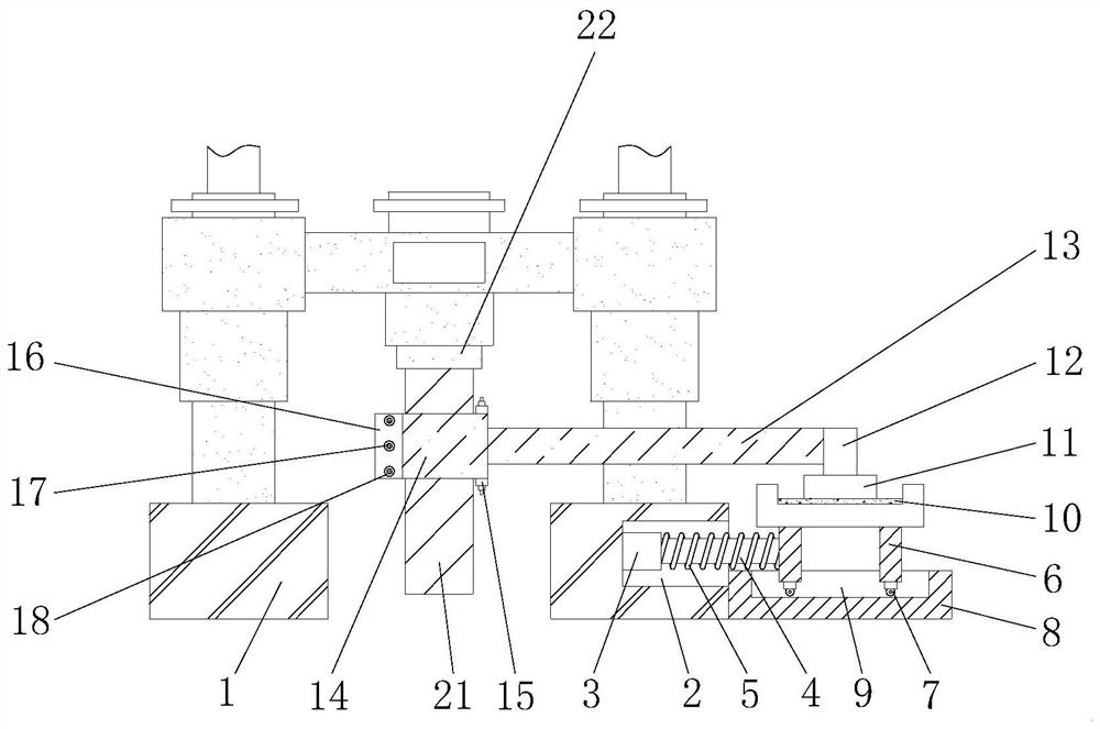
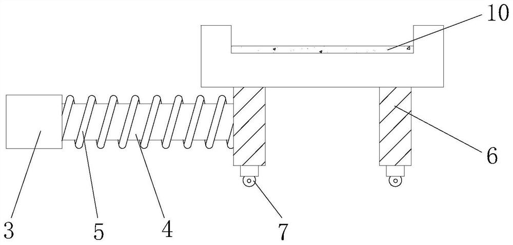
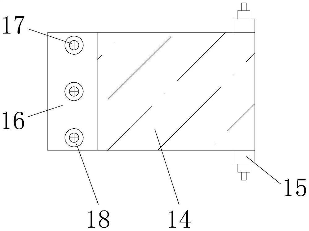
Drill rod conveying device and raise boring machine
A technology for conveying devices and drill pipes, applied in the direction of drill pipes, drilling equipment, drill pipes, etc., can solve the problems of poor conveying effect, achieve good conveying effect, fast and convenient process, and reduce the use cost
- Summary
- Abstract
- Description
- Claims
- Application Information
AI Technical Summary
Problems solved by technology
Method used
Image
Examples
Embodiment 2
[0034] During the drilling operation, the broken cuttings are washed by the flushing fluid when the pilot hole is drilled, and the cuttings are lifted out of the borehole by the flushing fluid along the annular space between the drill pipe and the hole wall. The friction between the flushing fluid and the drill pipe can easily lead to poor slag discharge, and easily cause disturbance to the drill pipe, affecting the accuracy of drilling.
[0035] In order to solve the above problems, this embodiment provides a raise drilling machine, including the drill pipe conveying device provided in Embodiment 1, and also includes a friction-reducing drill pipe, refer to Figure 5 , the friction-reducing drill pipe includes: a rod body 110 , the inside of the rod body 110 is provided with a well-washing fluid flow path 111 arranged axially along the rod body 110 , and the outer surface of the rod body 110 is provided with a drag-reducing structure.
[0036] When working, the flushing fluid...
Embodiment 3
[0049] refer to Figure 9 , On the basis of Embodiment 2, the friction-reducing drill pipe in this embodiment further includes a stabilizing ring 130 , the stabilizing ring 130 is sleeved on the rod body 110 , and the outer diameter of the stabilizing ring 130 is larger than the outer diameter of the rod body 110 .
[0050] When the flushing fluid flows through the stabilizing ring 130 from bottom to top, the circumferential turbulent flow in the stabilizing ring 130 forms a liquid gasket. When the friction-reducing drill pipe deviates, the turbulent flow on the compressed side of the liquid gasket is close to the hole wall, and the liquid pressure Increase to align the reduced-friction drill pipe.
[0051] Specifically, the lower surface of the stabilizing ring 130 and the connecting portion of the rod body 110 have an excessively circular arc. The resistance of the stabilizing ring 130 to the flushing fluid is reduced through the arc transition.
[0052] More specifically,...
Embodiment 4
[0054] In this embodiment, the friction-reducing drill pipe of the raise drilling rig, on the basis of Embodiment 2, also includes a water flow direction sensor arranged on the surface of the rod body, and the water flow direction sensor sends the water flow direction signal to the controller, and the controller drives the The device adjusts the rotation angle of the turntable 120 so that the direction from the big end to the tip of the groove 121 is consistent with the direction of water flow. The flow direction of the water flow is sensed by the water flow direction sensor, so that the angle of the turntable 120 is automatically adjusted by the controller, which can automatically adapt to different working conditions.
[0055] More specifically, the rod body 110 is divided into multiple sections from top to bottom, each section is provided with a water flow direction sensor, and the controller independently controls the direction of the turntable 120 in the corresponding sect...
PUM
 Abstract
Description
Claims
Application Information
 - R&D
- Intellectual Property
- Life Sciences
- Materials
- Tech Scout
- Unparalleled Data Quality
- Higher Quality Content
- 60% Fewer Hallucinations
Browse by: Latest US Patents, China's latest patents, Technical Efficacy Thesaurus, Application Domain, Technology Topic, Popular Technical Reports.
© 2025 PatSnap. All rights reserved.Legal|Privacy policy|Modern Slavery Act Transparency Statement|Sitemap|About US| Contact US: help@patsnap.com


