Protection device used for assembling rotor blade with convex shoulders

A technology for rotor blades and protective devices, which is applied in the direction of blade support components, engine components, machines/engines, etc., which can solve problems such as no protection method, short assembly cycle, and damage to the shoulder of the blade pot, so as to avoid combined installation steps , Improve assembly efficiency and avoid direct contact

Pending Publication Date: 2021-06-11
AECC AVIATION POWER CO LTD
7 Cites 0 Cited by

AI-Extracted Technical Summary

Problems solved by technology

[0004] Due to the large production batch and short assembly cycle, the traditional assembly method is time-consuming and laborious, has poor reliability and has no effective protection method. Therefore, it is necessary to find an effective, simple and practical improvement ...

Method used

Step 3: realize clamping on the air intake edge of the rotor blade with shoulder by closing the folder 4, and simultaneously fix the bayonet 1 on the root of the shoulde...

Abstract

The invention discloses a protection device used for assembling a rotor blade with convex shoulders, and belongs to the technical field of assembling processes of rotor blades with convex shoulders of aero-engines. The protection device used for assembling the rotor blade with the convex shoulders comprises a protection part, a clamping opening is formed in one end of the protection part, and a tightening part is arranged at the other end of the protection part. The clamping opening is used for being fixed to the convex shoulder root on the rotor blade with the convex shoulders, and the tightening part is used for being detachably connected with the air inlet edge of the rotor blade with the convex shoulders. The protection part, the clamping opening and the tightening part are integrally connected. The protection part is of a protection plate structure, the tightening part is of an inclined plane structure, and the protection part and the tightening part form a closing clamp-shaped body. According to the protection device used for assembling the rotor blade with the convex shoulders, the protection device can be completely attached to the molded surface of the blade, direct contact between a blade basin convex shoulder and a blade back convex shoulder is avoided, and finally zero-damage assembling of the rotor blade with the convex shoulders is achieved.

Application Domain

Blade accessoriesMachines/engines

Technology Topic

Structural engineeringAviation +2

Image

  • Protection device used for assembling rotor blade with convex shoulders
  • Protection device used for assembling rotor blade with convex shoulders

Examples

  • Experimental program(1)

Example Embodiment

[0029] In order to better understand the present invention, the technical solutions in the embodiments of the present invention will be described in connection with the drawings in the embodiments of the present invention, and the embodiments described herein will be clearly understood. It is an embodiment of the invention, not all of the embodiments. Based on the embodiments in the present invention, those of ordinary skill in the art will belong to the scope of the invention in the present invention without making in the pre-creative labor premise.
[0030] It should be noted that the specification and claims of the present invention and the terms "first", "second", "second" or the like are used to distinguish a similar object without having to describe a particular order or ahead order. It should be understood that the data such as use can be interchanged in place so that the embodiments of the invention described herein can be implemented in the order other than those illustrated or described herein. Moreover, the terms "including" and "having" and any variations are intended to cover non-rowing, such as process, methods, systems, products, or equipment that contain a series of steps or units, including a series of steps or units, not necessarily limited to clearly These steps or units may include other steps or units that are not clearly listed or for these processes, methods, products, or equipment.
[0031] The present invention will be further described below with reference to the specific embodiments and the accompanying drawings:
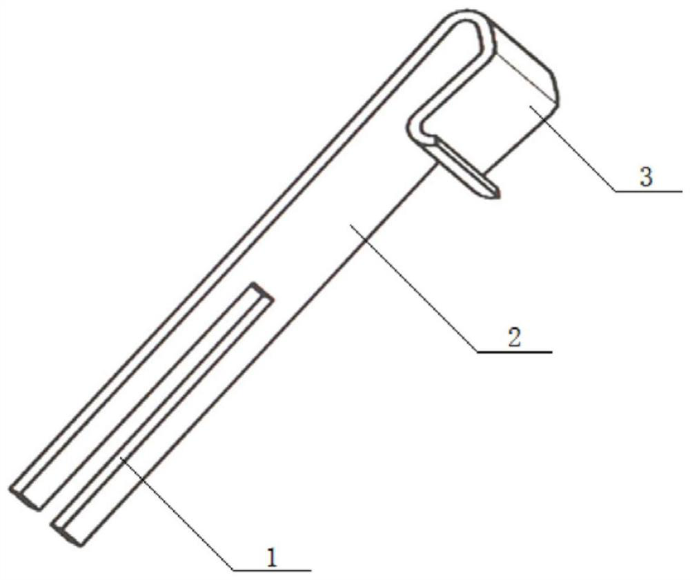
[0032] The present invention discloses a protective device for assembly with shoulder rotor blade, see figure 1 It can be seen that its structure includes a guard portion, and one end is provided with a tab 1, and the bayonet 1 is provided with a chamfer, the bracket opening, which is buffered; the other end of the protective portion is tightened. Department, the guard unit, the bayonet 1 and the tensioning portion integrated; the bayonet 1 is used to secure the shoulder root on the bell rotor blade, the heating portion for and convexes The intake side of the shoulder rotor blade is detachable.
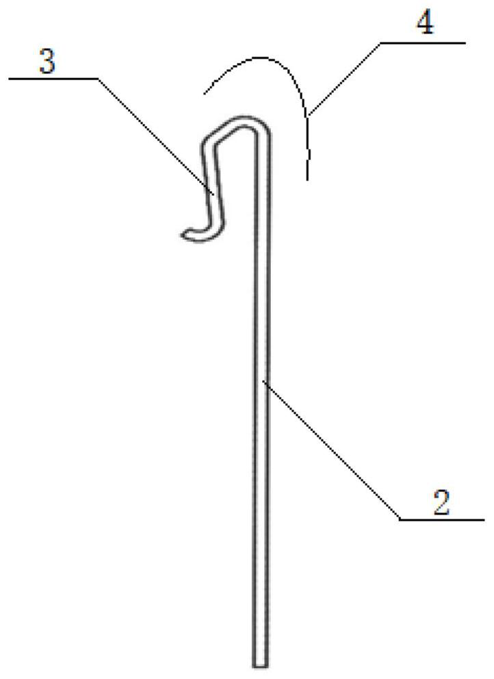
[0033] Among them, see figure 2 It can be seen that the protective portion is a protective plate 2 structure, the heating portion being a bevel 3 structure, the guard portion and the heating portion constitutes a clipped body 4; through the clipped body 4 clamping on the belt shoulder The intake edge of the rotor blade, the inclined surface structure is close to the inner side surface of the belt shoulder rotor blade.
[0034] Among them, the protective portion, the bayonet 1 and the heating portion are made of a polymeric material.
[0035] Specifically, the polymeric material is optional as PE, PVC or PTFE, or the like.
[0036] Specifically, the thickness of the protective plate 2 has a thickness of 0.8 to 1.5 mm.
[0037] Specifically, the width of the bayonet 1 is 4.24 to 5.4 mm.
[0038] The above-described above-described prevention device for assembling the shoulder rotor blade, can reduce the beetle damage ratio of the shoulder root on the carrier rotor blade to zero in the conventional assembly method, in the present invention In the way, it is made, used and installed, followed by step:
[0039] Step 1: Rough estimation of the shoulder root on the shoulder rotor blade easily generates the area of ​​the brown injury, select the matching guard 2 structural area;
[0040] Among them, there is a need to measure the actual length size of the blade intake edge to the shoulder root on the shoulder rotor blade; measure the actual thickness dimension of the intake side to the shoulder side shoulders; measure the blade intake edge test 5 ~ 12mm actual thickness dimension;
[0041] Step 2: Based on the shoulder thickness and shoulder root in the belt shoulder rotor blade, select 1 mm thick polyethylene material plate, select the matching bayonet 1 width, select the matching bevel 3 structure, where the beveled 3 and protection The plate 2 constitutes a protective device that is targeted to fabricate the use of shoulder rotor blade assembly of the present invention;
[0042]Step 3: Facing the intake side of the carrier rotor blade is realized by the clutch 4, while securing the bayonet 1 in the shoulder root on the shoulder rotor blade to ensure that the present invention is used to bump. Shoulder rotor blade assembled protective device is firmly stable and stable;
[0043] Step 4: Apply the leafbasin shoulder root of each blade to the protective device, and the blade shoulders will not contact each other, and it will not produce brown injury.
[0044] Specifically, in other embodiments of the present invention, the protective device for assembled with shoulder rotor blade is made of molding.
[0045] In the above embodiment, after the protective device according to the present invention is used in the protective device assembled by the shoulder rotor blade, it is possible to avoid the problems of the leafbasin shoulder and shoulder, which is easy to produce brushed shoulder. It is important to use the protective device, not only reduce the blade damage rate to zero, but also saves the time in the traditional assembly method needs to be repaired again, and can greatly improve production efficiency and reduce labor costs.
[0046] The above is merely illustrative of the technical idea of ​​the present invention, and it is not possible to define the scope of the invention. Within the protection range.

PUM

PropertyMeasurementUnit
Thickness0.8 ~ 1.5mm
Width4.24 ~ 5.4mm

Description & Claims & Application Information

We can also present the details of the Description, Claims and Application information to help users get a comprehensive understanding of the technical details of the patent, such as background art, summary of invention, brief description of drawings, description of embodiments, and other original content. On the other hand, users can also determine the specific scope of protection of the technology through the list of claims; as well as understand the changes in the life cycle of the technology with the presentation of the patent timeline. Login to view more.

Similar technology patents

Capacitor pulse voltage testing device and method

PendingCN106970308ARealize automatic switching controlavoid direct contact
Owner:广州泰络电子科技有限公司

Heating module of multi-layer composite structure and electronic cigarette device

PendingCN109820252Aavoid direct contactavoid chemical reactions
Owner:杭州森翼科技有限公司

Novel film-coated plugging disc

Owner:NINGBO DIOCHANGE MEDICAL TECH CO LTD

Classification and recommendation of technical efficacy words

  • avoid direct contact

Liquid crystal display panel

Owner:HONG FU JIN PRECISION IND (SHENZHEN) CO LTD +1

Functional enterostomy cannula

InactiveCN105708608AGood tissue compatibilityavoid direct contact
Owner:AFFILIATED HUSN HOSPITAL OF FUDAN UNIV

Refrigerator

ActiveCN102620499Aavoid direct contactImprove freshness preservation performance
Owner:HEFEI MIDEA REFRIGERATOR CO LTD

Endoscope microcapsule robot

InactiveCN103393389Aavoid direct contact
Owner:HARBIN INST OF TECH SHENZHEN GRADUATE SCHOOL
Why Eureka
Try Eureka