Industrial gas low-nitrogen energy-saving burner
An industrial gas and burner technology, applied in the directions of gas fuel burners, burners, combustion methods, etc., can solve the problems of shortening the service life of the burner, wasting energy, and high nitrogen content in the combustion exhaust.
- Summary
- Abstract
- Description
- Claims
- Application Information
AI Technical Summary
Problems solved by technology
Method used
Image

Examples
Embodiment Construction
[0036] The preferred embodiments of the present invention will be described below in conjunction with the accompanying drawings. It should be understood that the preferred embodiments described here are only used to illustrate and explain the present invention, and are not intended to limit the present invention.
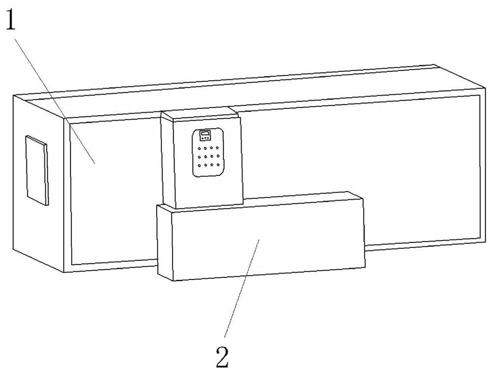
[0037] Please see all the drawings, an industrial gas low nitrogen energy-saving burner, including:
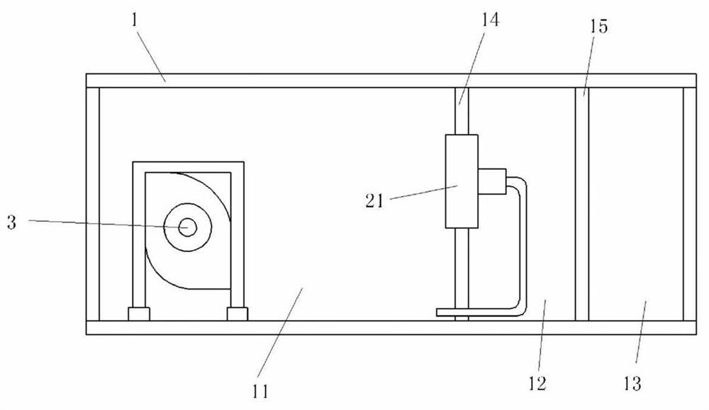
[0038] The box body 1 is internally divided into a combustion chamber 11, a mixing chamber 12, and a clean air chamber 13;
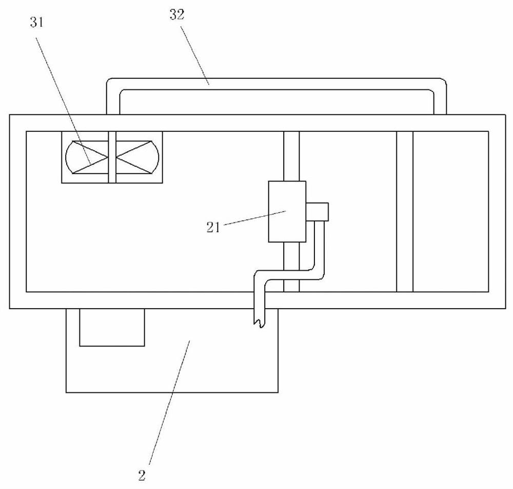
[0039] The gas pipeline module 2 is placed outside the box body 1, and the gas pipeline module 2 communicates with the mixing chamber 12;
[0040] The circulation device 3 is arranged in the combustion chamber 11 , and the circulation device 3 communicates the combustion chamber 11 with the clean air chamber 13 .
[0041] As an embodiment of the present invention, the inside of the box 1 is fixedly provided with a windshield 14 and an exhaust...
PUM
 Abstract
Description
Claims
Application Information
PatSnap Eureka turns technology decisions into work you can execute. Powered by our Innovation Knowledge Graph, it runs expert workflows across engineering, life sciences, materials and intellectual property. Get your review-ready output in minutes.


