Platform jig for efficiently detecting straightness and detection method thereof

A technology for detecting straightness and straightness, applied in the direction of angle/taper measurement, etc., can solve the problems affecting the accuracy of detection results, low detection efficiency, deformation of the flat ruler, etc., to improve detection efficiency and detection accuracy, accurate measurement results, improve The effect of detection accuracy

Pending Publication Date: 2021-06-11
上伟(江苏)碳纤复合材料有限公司
View PDF1 Cites 0 Cited by
  • Summary
  • Abstract
  • Description
  • Claims
  • Application Information

AI Technical Summary

Problems solved by technology

[0008] The purpose of the present invention is to provide a high-efficiency detection straightness platform jig to solve the problems of low detection efficiency when using a flat ruler to detect straightness, and the deformation and wear of the flat ruler, which affects the accuracy of the detection results.

Method used


Image

  • Platform jig for efficiently detecting straightness and detection method thereof
  • Platform jig for efficiently detecting straightness and detection method thereof
  • Platform jig for efficiently detecting straightness and detection method thereof

Examples


Embodiment 1

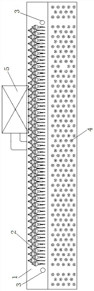
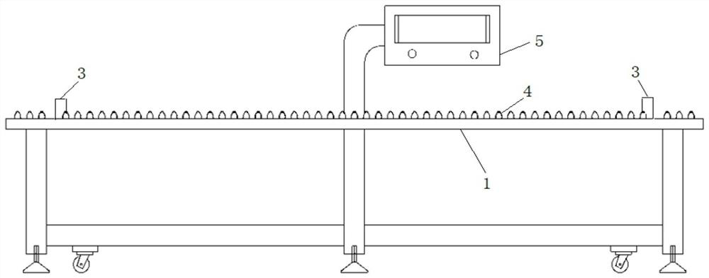
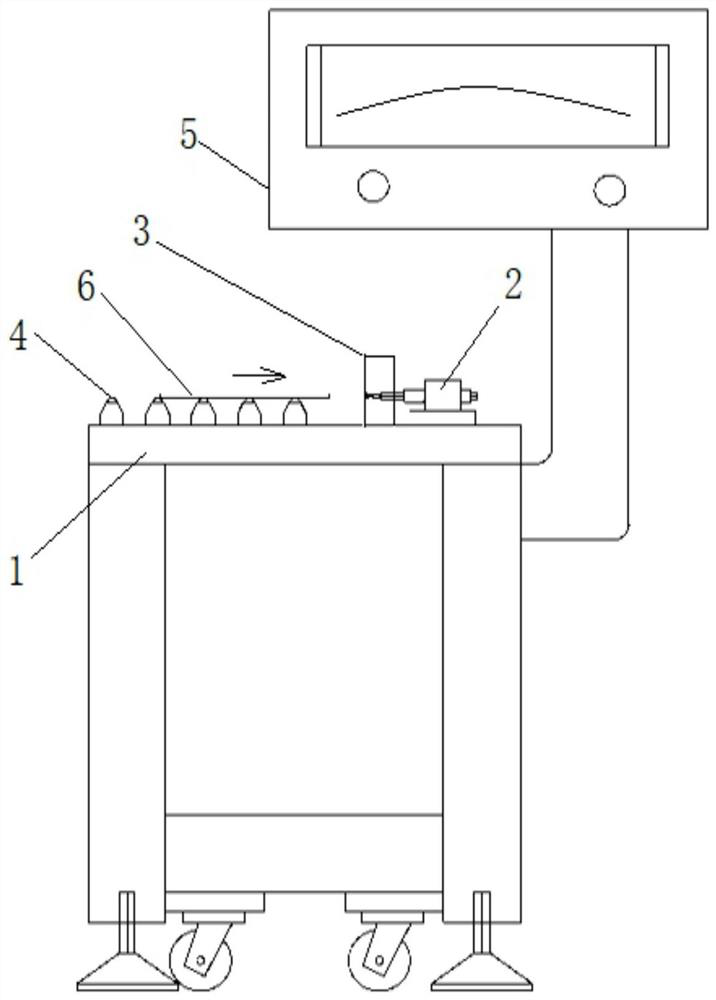
[0044] Such as Figure 1 to Figure 3 As shown, a high-efficiency detection straightness platform fixture includes a workbench 1, a micrometer 2, and a supporting block 3.

[0045] The workbench 1 is used to support the workpiece 6 to be detected (such as a pultruded plate); the workbench 1 is supported by a stand, and cup feet and rollers are installed on the bottom of the stand. Several universal balls 4 are installed in front of the micrometer 2 on the workbench 1. The height of each universal ball 4 is the same. When feeding, there is rolling friction between the universal balls 4 and the workpiece 6 to ensure smooth and flexible loading. , efficient.

[0046] The micrometer 2 is used to measure the straightness of the workpiece, and the Sivaka 232 interface percentage micrometer or other types of micrometers can be selected. A row of micrometers 2 is installed on the workbench 1 along a straight line, and the probes of the micrometers 2 face the workpiece 6; each microme...

Embodiment 2

[0053] The difference between this embodiment and embodiment 1 is that, as Figure 6 As shown, a verification mechanism is also installed on the workbench 1 to verify whether the probes of each micrometer are on the same straight line. The verification mechanism includes a rope body 7, a bobbin 8, a tension gauge 9, a fixed pulley 10, and a fixed block 11. The bobbin 8 and the fixed block 11 are respectively located on the left and right sides of a row of micrometers 2, and a non-return bearing is installed in the bobbin 8. To tighten the rope body 7 at any time. The fixed pulley 10 is located on the right side of the fixed block 11 , and the tension gauge 9 is installed between the fixed block 11 and the fixed pulley 10 . One end of the rope body 7 is fixed on the bobbin 8, the rope body 7 is tensioned on the two supporting blocks 3, and the rope body 7 bypasses the fixed pulley 10 and then connects the tension meter 9, and the tension meter 9 uses the set tension value to ...

Embodiment 3

[0056] The difference between this embodiment and embodiment 2 is that, as Figure 7 and Figure 8 As shown, an anti-collision mechanism is installed in front of the two supporting blocks 3 on the workbench to prevent the workpiece 6 from colliding with the measuring head of the micrometer 2 before contacting the supporting blocks 3 . The anti-collision mechanism includes a baffle plate 12 and a transmission mechanism. A positioning hole adapted to the baffle plate 12 is provided on the workbench 1, and the baffle plate 12 moves up and down along the positioning hole; The shutter 12 is raised and the shutter 12 is lowered during testing.

[0057] Specifically, the transmission mechanism includes a translation drive member 13 , a pull rod 14 , a guide block 15 , a cam bearing follower 16 and a transmission column 17 . The translation driver 13 is drivenly connected to the pull rod 14 to drive the pull rod 14 to reciprocate in the left and right directions, and the translation...


PUM


Abstract

The invention provides a platform jig for efficiently detecting straightness and a detection method thereof, and the platform jig comprises a workbench which is used for supporting a to-be-detected workpiece; micrometer gauges which are used for measuring the straightness of the workpiece, wherein a row of micrometer gauges are installed on the workbench in the direction of a straight line, and measuring heads of the micrometer gauges face the workpiece, and each micrometer is connected with a data processing display system through a data line; bearing blocks which are located on the left side and the right side of the row of the micrometers respectively, wherein the front end faces of the bearing blocks and the measuring heads of the micrometers are located on the same straight line, and the workpiece abuts against the front end faces of the bearing blocks during detection. The problems that the detection efficiency is low when a leveling ruler is used for detecting the straightness, and the accuracy of the detection result is affected due to deformation and abrasion of the leveling ruler are solved.

Description

technical field [0001] The invention belongs to the technical field of plate straightness detection, and in particular relates to a platform jig for high-efficiency detection of straightness and a detection method thereof. Background technique [0002] The composite material used for wind turbine blades is pultruded sheet. The basic requirement of pultruded sheet is that it cannot be bent or close to straight. After the sheets are laminated, the smaller the gap, the better the structural strength of the product can be guaranteed. Therefore, the accuracy of plate straightness measurement is very important, and it is an important basis for judging whether the product is qualified. [0003] The patent document of our company whose publication number is CN208398790U discloses a carbon fiber board straightness detection tool, including a detection platform, a reference plate is arranged on the upper side of the detection platform along the length direction, the reference plate is...

Claims


Application Information

Patent Timeline
IPC IPC(8): G01B5/25
CPCG01B5/25
Inventor 王树春王成军陈海萍郭华轩
Owner 上伟(江苏)碳纤复合材料有限公司
Why Eureka
Try Eureka