Wrapping post structure, carrier, lens driving device, photographic device and electronic product

A winding post and carrier technology, which is applied in the field of photographic devices, lens driving devices, electronic products, winding post structures, and carriers, and can solve the problems affecting the accuracy of the lens driving device, affecting the assembly of the lens driving device, and difficult to control the flow of solder paste, etc. problem, to avoid the center of gravity shift of the carrier, reduce the difficulty of injection molding processing, and avoid the effect of warping

Active Publication Date: 2021-06-11
NEW SHICOH MOTOR CO LTD
View PDF5 Cites 3 Cited by
  • Summary
  • Abstract
  • Description
  • Claims
  • Application Information

AI Technical Summary

Problems solved by technology

[0003] When soldering between the winding post and the pad, too much solder paste will easily cause the pad to lift, which will cause the pad to be higher than the surface of the spring, which will affect the assembly of the lens driver, or the solder paste will flow to both sides of the wire head position, and It is difficult to control the flow direction of solder paste, which will easily lead to the deviation of the center of gravity of the carrier and affect the accuracy of the lens driving device

Method used


Image

  • Wrapping post structure, carrier, lens driving device, photographic device and electronic product
  • Wrapping post structure, carrier, lens driving device, photographic device and electronic product
  • Wrapping post structure, carrier, lens driving device, photographic device and electronic product

Examples


Embodiment 2

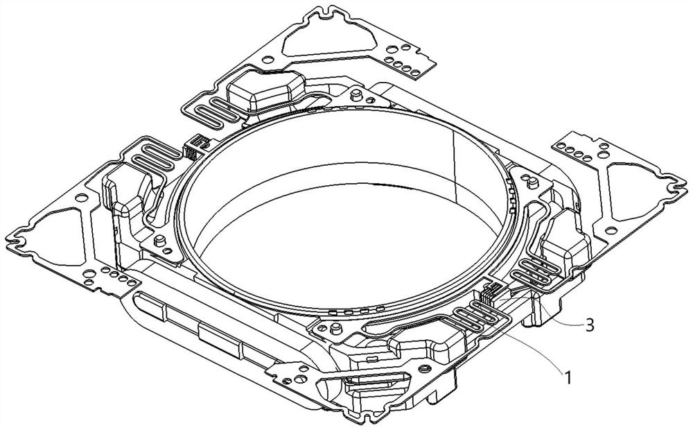
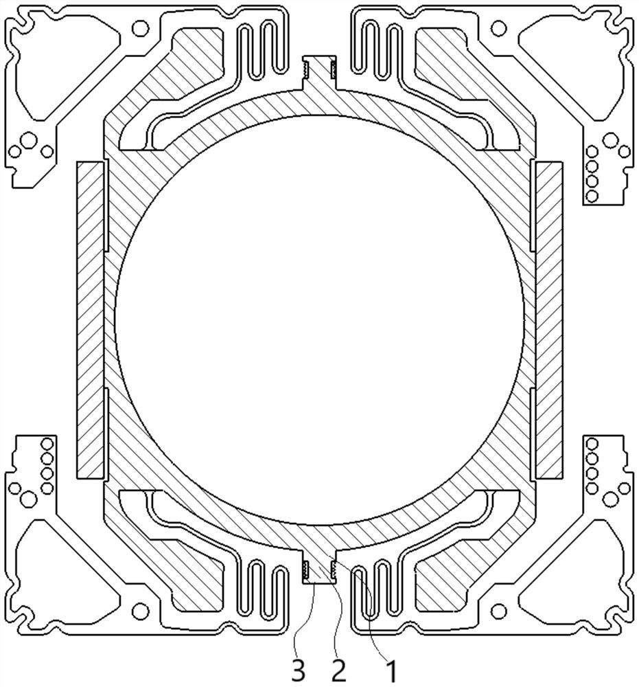
[0037] Embodiment 2: a kind of carrier, such as Figure 7 and Figure 8 As shown, it has the winding post structure described in Embodiment 1, and in this embodiment, the winding post structures are arranged in two groups and arranged symmetrically. This embodiment also includes a carrier body 5, the carrier body 5 is integrally formed with a stepped portion 6 connected to the fixed portion 1, the stepped portion 6 extends to a position of the fixed portion 1 close to the winding portion 2, and is wound around the winding portion 2. The coil wire ends of the portion 2 are attached to the stepped portion 6 .

[0038] Through the integral injection molding of the step part 6 and the fixing part 1, the connection strength between the winding post and the carrier is effectively increased, and at the same time, the difficulty of injection molding of the winding post is reduced. In addition, the step part 6 facilitates winding of the coil end on the winding part 2 .

Embodiment 3

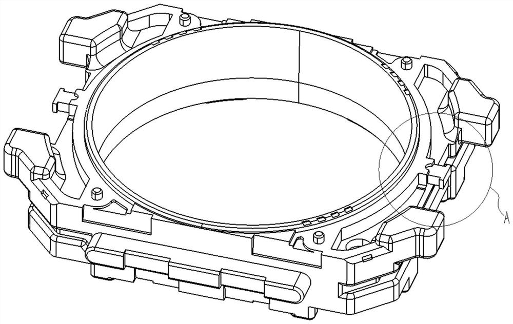
[0039] Embodiment 3: a kind of lens driving device, such as Figure 9 As shown, it has the carrier described in Embodiment 2. Specifically, the lens driving device has the carrier body 5 in Embodiment 2 and the winding post structure disposed on the carrier body 5 . The lens driving device with the above structure ensures that the center of gravity of the carrier is located at the center of the carrier, improves the accuracy of driving the lens movement, and ensures that the lens moves along the optical axis, thereby effectively improving the quality of photographing.

Embodiment 4

[0040] Embodiment 4: a kind of camera device, such as Figure 10 As shown, there is the lens driving device described in Embodiment 3. In the embodiment, the driving structure in the lens driving device drives the corresponding lens to move to achieve focusing. After focusing, the light passes through the lens and enters the photoelectric sensor in the camera device and is converted into an electrical signal, so that the image of the collected photo is converted into electronic data. camera function. The lens driving device and the spring structure in the camera device in this embodiment have been fully described above, and will not be repeated here.


PUM


Abstract

The invention discloses a wrapping post structure, a carrier, a lens driving device, a photographic device and an electronic product, and the key points of the technical scheme are that the wrapping post structure comprises a fixed part fixed on the carrier, and one end, deviating from the carrier, of the fixed part is integrally provided with a winding part for winding the end part of a coil; the sectional area of the winding part is smaller than that of the fixed part, one end, far away from the fixed part, of the winding part is provided with an anti-falling part, the surface of one side, facing a bonding pad, of the anti-falling part and a coil head lower than the winding part face the surface of the bonding pad, and the distance between two side walls of the anti-falling part is larger than that between two side walls of the winding part. The surface, facing the bonding pad, of the fixed part is higher than the coil end of the winding part or the coil end of the winding part. The structure effectively avoids the tilting of the bonding pad caused by excessive solder paste during tin soldering, controls the flow direction of the solder paste, and ensures that the center of gravity of the carrier after tin soldering is located at the center of the carrier.

Description

technical field [0001] The invention relates to the field of photographic equipment, in particular to a winding post structure, a carrier, a lens driving device, a photographic device and electronic products. Background technique [0002] The existing lens driving device mainly includes a housing, a base, a carrier, a spring (a lower spring, an upper spring), a magnet, and a coil. The coil is generally wound around the carrier and electrically connected to the spring, and the spring is provided with a pad, and the carrier is provided with a winding post for winding the end of the coil, and soldering is performed between the pad and the winding post to realize the connection between the pad and the coil and fixed. [0003] When soldering between the winding post and the pad, too much solder paste will easily cause the pad to lift, which will cause the pad to be higher than the surface of the spring, which will affect the assembly of the lens driver, or the solder paste will ...

Claims


Application Information

Patent Timeline
Patent Type & Authority Applications(China)
IPC IPC(8): G02B7/04H02K3/50
CPCG02B7/04H02K3/50
Inventor 靖二勇易长飞
Owner NEW SHICOH MOTOR CO LTD
Why Eureka
Try Eureka