
Power cable insulation closed terminal and closing method of cable end

A power cable and cable insulation technology, which is applied to cable terminals, cable installation, cable accessories, etc., can solve the problems of inconvenient operation of electric field insulation and sealing, and achieve the effect of saving cable length, occupying less land and small size.

Inactive Publication Date: 2021-06-11
SHANGHAI ELECTRICGROUP CORP
View PDF6 Cites 0 Cited by
  • Summary
  • Abstract
  • Description
  • Claims
  • Application Information

AI Technical Summary

Problems solved by technology

[0003] The technical problem to be solved by the present invention is: it is inconvenient to operate the electric field insulation sealing at the other end of the cable (non-high-voltage lead wire side) during the high-voltage test of the cable or accessories, and at the same time reduce the consumption length of the cable and save the operating space

Method used


Image

  • Power cable insulation closed terminal and closing method of cable end
  • Power cable insulation closed terminal and closing method of cable end

Examples


Embodiment Construction

[0022] In order to make the present invention more comprehensible, preferred embodiments are described in detail below with accompanying drawings.

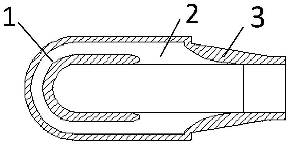
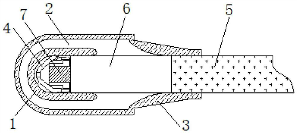
[0023] Such as figure 1 with figure 2 As shown, an insulated closed terminal of a power cable according to the present invention includes an inner shielding layer 1 , an insulating layer 2 , an outer shielding layer 3 and a metal shielding cover 4 . The inner shielding layer 1 and the outer shielding layer 3 are made of semi-conductive rubber material, and the insulating layer 2 is made of insulating rubber material. These three parts form an integral part through the rubber injection process and become the main body of the cable closed insulation terminal. The outer shielding layer 3 , insulating layer 2 and inner shielding layer 1 are sequentially arranged from outside to inside to form a semi-closed structure with one end open.

[0024] The metal shield 4 is a matching part. The metal shield 4 is set on the cable conductor 7...


PUM


Abstract

The invention discloses a power cable insulation closed terminal and a closing method of a cable end. The power cable insulation closed terminal structurally comprises an outer shielding layer, an insulating layer and an inner shielding layer, wherein the outer shielding layer, the insulating layer and the inner shielding layer are sequentially arranged from outside to inside to form a semi-closed structure with an opening at one end; and the inner shielding layer, the insulating layer and the outer shielding layer are integrally prefabricated together, the electric field distribution is uniform, and the performance is reliable. The power cable insulation closed terminal can be conveniently sleeved into the end part of a cable, plays a role in sealing a high-voltage electric field, ensures that a withstand voltage test is smoothly carried out, and ensures the safety of personnel at the end part of the cable. When in use, the inner shielding layer is sleeved on a cable conductor, the closed end of the inner shielding layer is in contact with the cable conductor, and the opening end of the inner shielding layer is in insulation lap joint with the cable; the opening end of the outer shielding layer is in lap joint with the outer shielding layer of the cable, and the insulating layer is arranged between the outer shielding layer and the inner shielding layer and is attached to the cable in an insulating mode; and finally, the outer shielding layer is grounded.

Description

technical field [0001] The invention relates to an insulating closed terminal of a power cable and a closing method of a cable end, belonging to the field of power cables and accessories. Background technique [0002] In the field of power cables and accessories, when the cables and accessories are subjected to high-voltage withstand tests, the traditional method is: use two sets of test water terminals at both ends of the cable or use an open cable terminal at one end, and the other end is sealed with a GIS terminal gas chamber. . In such a way for high-voltage tests, the length of the wasted cable is large, and the installation and operation are inconvenient. Contents of the invention [0003] The technical problem to be solved by the present invention is: it is inconvenient to operate the electric field insulation sealing at the other end of the cable (non-high-voltage lead side) during the high-voltage test of the cable or accessories, and at the same time reduce the ...

Claims


Application Information

Patent Timeline
Patent Type & Authority Applications(China)
IPC IPC(8): H02G15/04H02G15/068
CPCH02G15/043H02G15/068
Inventor 杨建华程少勇周雁
Owner SHANGHAI ELECTRICGROUP CORP
Learn More