Combined electric control equipment room with moisture-proof function

An electronic control equipment, combined technology, applied in the direction of electrical equipment structural parts, electrical equipment shell/cabinet/drawer, electrical components, etc., can solve problems such as restricting the installation environment between equipment, performance failure and damage of electrical control boxes, etc. To achieve the effect of enhancing drying and dehumidification, preventing water backflow, and improving the sealing effect

Active Publication Date: 2021-06-11
山东中侨启迪环保装备有限公司
View PDF11 Cites 0 Cited by
  • Summary
  • Abstract
  • Description
  • Claims
  • Application Information

AI Technical Summary

Problems solved by technology

[0003] However, factors such as ventilation and moisture resistance are taken into account in the installation of the existing electronic control equipment room, which greatly limits the installation environment and location of the equipment room, and creates great restrictions on the layout and components of the electronic control equipment room. If the moisture-proof and rain-proof performance of the electronic control equipment is poor, if it is installed outdoors, it is easy to cause performance failure or damage to the built-in electric control box, and the electrical appliances are moisture-proof. From an economical point of view, moisture-proof agents are usually selected. Desiccant, desiccant, etc. are used to protect the electronic control components from moisture, but frequent replacement of moisture-proof agent, desiccant, etc. will not only cause complicated maintenance work, but also if they are not replaced in time, if the moisture-proof performance is reduced, the built-in electric control box will easily cause performance failure or damage. Case

Method used


Image

  • Combined electric control equipment room with moisture-proof function
  • Combined electric control equipment room with moisture-proof function
  • Combined electric control equipment room with moisture-proof function

Examples


Embodiment Construction

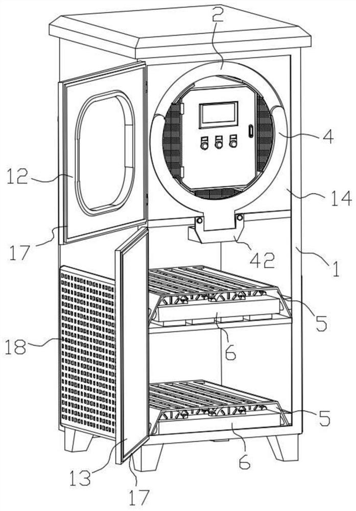
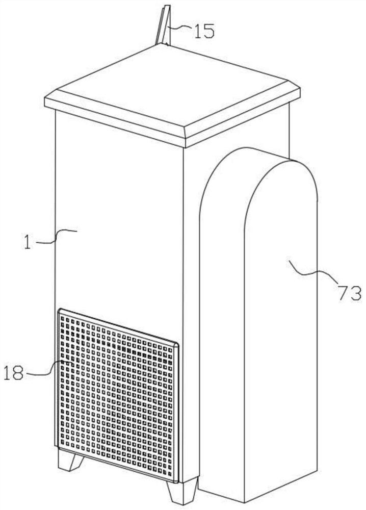
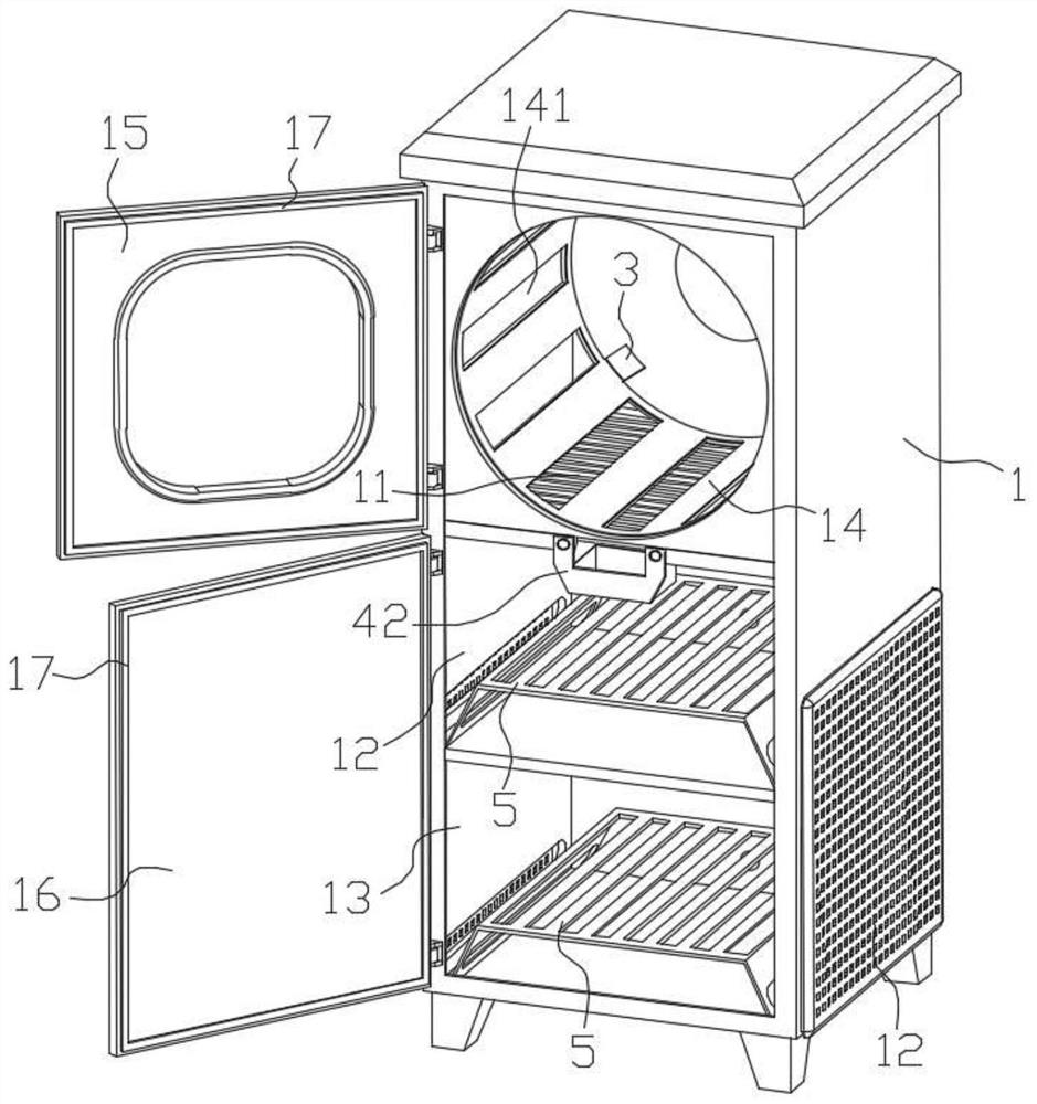
[0049] Such as Figure 1-3 As shown, a combined electronic control equipment room with a moisture-proof function includes: a box body 1 for carrying various components, and the box body 1 is separated from the top to the bottom by the partition plate to separate the electric control warehouse 11 and the first warehouse 12. In the second chamber 13, the left and right sides of the ventilation switching box 6 are respectively provided with a strip tube running through the box body 1, and a group of air filters 18 are respectively provided on the left and right sides of the box body 1 corresponding to the position of the strip tube. By arranging the air filter 18, it is possible to prevent large pieces of sundries and the like from entering the ventilation switching box 6 through the pipeline and affecting the switching effect of the ventilation switching box 6.

[0050] Such as figure 1 , 5 , As shown in 6-9, there is a ventilation cover 14 attached to the inner wall of the el...


PUM


Abstract

The invention discloses a combined electric control equipment room with a moisture-proof function, and the room comprises a box body formed by an electric control bin, a first bin chamber and a second bin chamber; a ventilation sleeve is arranged in the electric control bin, and an annular control is arranged on the inner ring surface of the ventilation sleeve; and a plurality of groups of first ventilation openings and second ventilation openings are correspondingly formed in the circumferential direction of the annular control and the ventilation sleeve; a group of supporting net plates and ventilation switching boxes are arranged on the inner bottom surface of each of the first chamber and the second chamber; the rear end face of the annular control piece is connected with a first transmission belt wheel through a rotating shaft, the rear ends of all rotating rods of the ventilation switching box are connected with branch belt wheels, a main belt wheel is arranged in the middle of the rear side face of the ventilation switching box and is in belt transmission with all the branch belt wheels through a transmission belt, and the rear end of the main belt wheel is connected with a second transmission belt wheel through a rod piece; the first transmission belt wheel and the second transmission belt wheel are driven through a transmission assembly. According to the device, ventilation and sealing in the box can be freely switched, accumulated water is prevented from flowing backwards, and the waterproof and moisture-proof effects are achieved.

Description

technical field [0001] The invention relates to the technical field of electric control equipment, in particular to a combined electric control equipment room with a moisture-proof function. Background technique [0002] The equipment room is the room where various equipment are installed. For the integrated wiring system project, it is mainly to install the wiring connection equipment. Communication equipment, computer network equipment, and building group wiring connection equipment are used for network management and information exchange. [0003] However, factors such as ventilation and moisture resistance are taken into account in the installation of the existing electronic control equipment room, which greatly limits the installation environment and location of the equipment room, and creates great restrictions on the layout and components of the electronic control equipment room. If the moisture-proof and rain-proof performance of the electronic control equipment is ...

Claims


Application Information

Patent Timeline
IPC IPC(8): H05K5/02H05K7/20B01D53/26
CPCH05K5/0213H05K5/0217H05K7/20127B01D53/26H05K5/03
Inventor 于安方刘怀文
Owner 山东中侨启迪环保装备有限公司
Why Eureka
Try Eureka