Anchor with suture

A technology of anchors and wires, which is applied in the field of medical devices, can solve the problems of hindering the fixation of the nail body and bone, damaging sutures, etc., and achieve the effects of reducing interference, improving strength, and reducing damage

Active Publication Date:
View PDF8 Cites 2 Cited by
  • Summary
  • Abstract
  • Description
  • Claims
  • Application Information

AI Technical Summary

Problems solved by technology

[0004] In view of the above-mentioned related technical solutions, the inventors found that: the suture thread passes through the peripheral surface of the nail body, and when the nail body is screwed into the bone, the suture thread will hinder the fixation of the nail body and the bone, and may damage the suture thread

Method used


Image

  • Anchor with suture
  • Anchor with suture
  • Anchor with suture

Examples


Embodiment 1

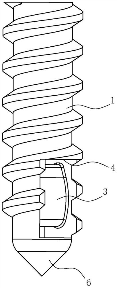
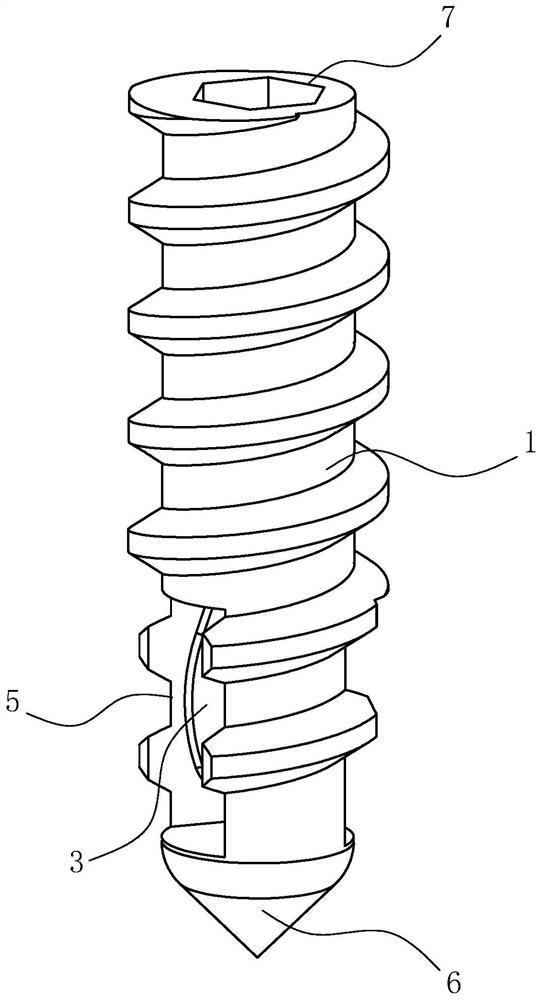
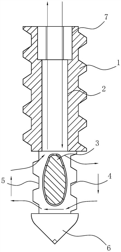
[0037] refer to figure 1 , figure 2 and image 3 , the present application provides a threaded anchor, comprising a cylindrical nail body 1, screw threads are provided on the peripheral surface of the nail body 1; The wire hole 2 and the receiving wire hole 2 only run through one end face of the nail body 1, that is, one end of the nail body 1 is an open end and the other end is a closed end; Two opposite surfaces are fixedly connected with the hole wall of the nanowire hole 2, and there is a gap for suture to pass between the peripheral surface of the threading block 3 and the hole wall of the nanowire hole 2, that is, the threading block 3 separates the inside of the nanowire hole 2 It is divided into two parts for sutures to pass through; the peripheral surface of the nail body 1 is provided with a first wire hole 4 and a second wire hole 5, and the first wire hole 4 and the second wire hole 5 are opened in the threading block 3. position and the first backguy hole 4 is...

Embodiment 2

[0052] refer to Figure 5 The difference between this embodiment and the first embodiment is that the shape of the threading block 3 is elliptical, and the major axis of the ellipse is parallel to the axis of the nail body 1 .

[0053] Due to the particularity of the ellipse shape, that is, the end of the ellipse along its long axis direction is relatively narrow, so when the free end of the suture enters the inside of the suture hole 2 and moves to a position close to the threading block 3, continue to place the The free end of the suture moves toward the direction close to the threading block 3 until the free end of the suture abuts against the end of the threading block 3. Since the end of the elliptical threading block 3 is narrow, when the free end of the suture and the threading block After the end of the block 3 abuts, one of the free ends of the suture automatically slides to one side of the threading block 3, without the need for the doctor to adjust the position of t...

Embodiment 3

[0055] refer to Figure 6 The difference between the present embodiment and the first embodiment is that the shape of the threading block 3 is rhombus, and the long diagonal of the rhombus is parallel to the axis of the nail body 1; the oval shape of the threading block 3 in this embodiment and the second embodiment A similar effect can be achieved and will not be repeated here. Of course, the threading block 3 can also be in the shape of a shuttle, a kite or any other irregular shape, as long as the above constraints on the shape of the threading block 3 can be met.


PUM


Abstract

The invention relates to the field of medical instruments, in particular to an anchor with a suture. The key points of the technical scheme are as follows: a nail body with threads on the peripheral surface, a suture containing hole for inserting a suture is formed in the nail body, and the suture containing hole penetrates through one end of the nail body; a suture penetrating block is arranged in the suture containing hole, and a gap allowing a suture to penetrate through is formed between the surface of the suture penetrating block and the hole wall of the suture containing hole; a first suture pulling hole communicated with the suture containing hole is formed in the circumferential surface of the nail body and is formed in the position where the suture penetrating block is located; so that the interference of the suture on the fixation of the nail body on the bone is reduced and the damage to the suture is reduced.

Description

technical field [0001] The present application relates to the field of medical devices, in particular to a threaded anchor. Background technique [0002] In the process of soft tissue repair, the doctor connects the soft tissue with sutures, and the sutures are brought in and fixed on the bone surface through anchors with wires, so that the soft tissues and bones are fixed. [0003] A screw-in threaded anchor described in the related art includes a nail body, a thread is provided on the peripheral surface of the nail body, and a through hole is provided on the peripheral surface of the nail body for the suture to pass through; the commonly used surgical operation The diameter range of the suture is 0.500-0.599mm; before the operation, one end of the suture is inserted into the through hole of the nail body to fix the position between the suture and the nail body, and then the screw tap or other tools are used on the bone A threaded hole matching the nail body is opened on t...

Claims


Application Information

Patent Timeline
Patent Type & Authority Applications(China)
IPC IPC(8): A61B17/064A61B17/06A61B17/04
CPCA61B17/0642A61B17/06166A61B17/0401A61B2017/0648A61B2017/0446A61B2017/0408
Inventor 孔庆俊黎建波王巨伟
Why Eureka
Try Eureka